Ken Reynolds, ProPhotonix
A discussion of the limitations of traditional sun-simulator technologies and the advantages offered by LED systems, with a review of LED-based system
design characteristics and cost benefits.
Sun simulators – instruments that provide illumination approximating natural sunlight under controlled, repeatable laboratory or production line conditions – are used primarily for testing solar cells and modules by measuring their electrical characteristics. The technology also is used for tests of sunlight weather conditions and of durability upon exposure to the natural environment for paint, coatings, plastics, glass and other materials. They can be used to study sleep and human productivity, seasonal affective disorder and jet lag, and the effect of sunlight on recovery from surgery and illness. Sun-simulation lamps also can enhance growth in agriculture and aid yield in animal and fish farming. Sun-simulator methodologies recently have been adopted in architectural lighting for domestic, hospitality and entertainment settings.
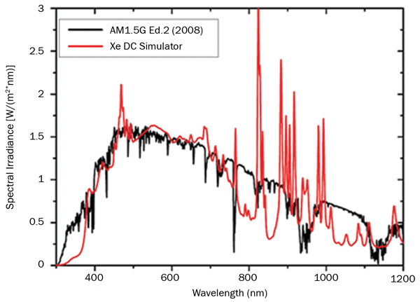
Traditionally, sun-simulator illumination has been supplied by xenon short-arc lamps and metal halide discharge lamps (Figure 1). Recent advances in high-power LED technology have resulted in a number of LED-based sun simulators coming to market. LED sources provide users with greater opportunity to optimize their desired spectrum and monitor it in real time. This is critical in a test environment where accurate spectral matching and controlled real-time power management lead to greater manufacturing production and test efficiencies. LED-based sun simulators’ principal strength is that they can be designed with finely tuned spectra with precisely controlled high-speed modulation.

Figure 1. Comparison between the sun spectrum of a traditional xenon lamp and standard sunlight at ASTM G-173 AM 1.5. Image courtesy of Fraunhofer Institute.
In this article, we first will discuss the limitations of traditional sun-simulator technologies and the advantages offered by LED-based systems. We will review the LED-based system design characteristics, including spectral accuracy and intensity specifications, and how they affect the number of wavelengths utilized, the device choices and the overall optical design. Also, we will cover various electronic options and functionalities, with a particular focus on calibration and long-term sun-simulator spectrum consistency. Finally, we will address a realistic cost and cost benefit of LED systems in comparison to traditional systems.
Traditional technologies, emerging requirements
Xenon and metal halide lamps have short lifetimes requiring frequent replacement (<10,000 hours). This makes the lamps an unsatisfactory tool for lifetime-measurement applications. These lamps are
not “instant on,” so they require a couple of minutes to warm up and cool down, adding to the operating cost. As a result, while the up-front cost of the lamps is relatively cheap, the cost of ownership over their lifetimes is high when you factor in acquisition and running costs, maintenance and safe disposal.

Sun spectrum standards, set by IEC and ASTM International, are a common specification for sun simulators (Table 1). The light from a sun simulator is controlled in three dimensions: spectral content, spatial uniformity and temporal stability. Each dimension is classified as A, B or C. The specifications required for each class are defined in Table 1. A sun simulator meeting Class A specifications in all three dimensions is referred to as
a Class A sun simulator or sometimes a Class AAA.
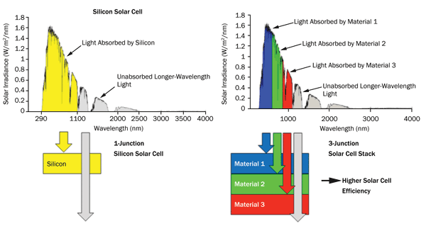
The sun spectrum contains photons of different energy based on different wavelengths. The most common solar cell technologies are based on single-junction architectures that have a limited range of wavelengths that convert electromagnetic radiation into electrical energy (Figure 2a). If light is not generated in a specific junction frequency range, solar cell energy output is limited. Next-generation multijunction solar cells comprise multiple individual solar cells grown on top of each other so that together they can absorb a wider range of the sun spectrum1 (Figure 2b). This is achieved by designing junctions to absorb increasingly narrow segments of the solar spectrum. Each junction’s material structure has been individually tailored to maximize the efficiency for its particular wavelength range so that manufacturers can drive solar cell efficiencies much higher than was previously possible. Each subcell is composed of a unique material that absorbs a specific portion of the sun spectrum. The top cell absorbs blue light, while the bottom cell absorbs infrared light. The majority of the work so far has concentrated on three-junction solar cells, but four-, five- and six-junction solar cells are in development.

Figure 2. (a) Single-junction solar cell; (b) Multijunction solar cell.3 Image courtesy of Solar Junction
These new technologies have dramatically changed the operational requirements of sun simulators. Users require more functionality and control of the optical output from sun simulators. LED-based simulators have been developed to run continuously over a long period of time, or to be flashed for short periods of time. LED technologies allow for easy manipulation and control of the flash frequencies, intensities and shapes. Simulators can even be designed to have different output profiles across different regions. “Recipes” can be designed, stored and easily manipulated via a graphical user interface. Thus, LED-based sun simulators provide precision control and high intensity, offering a superior technology for many applications.
LED sun simulators: advantages

Chip-on-board LED technology describes the mounting of a bare LED chip in direct contact with the substrate to produce LED arrays. It provides advantages over traditional surface-mount LED technology in that the packing density of the LEDs is much higher. This contributes to higher intensity, improved uniformity and a more compact package than would be achievable with surface-mount LED technology.
These devices can be implemented into various form factors via a number of packaging methods, allowing much greater design flexibility (Table 2) and resulting in greater spectrum accuracy and uniformity.
The light-output intensity of LEDs can be precisely controlled to within microseconds, ensuring that the desired emission spectrum is achieved. Using electronic software control, the light-output intensity of the LEDs can be kept stable for a long time. Importantly, this level of control is scalable for systems ranging from a couple of LEDs to thousands of LEDs. For larger systems, it is more common to control groups of LEDs, rather than individual LEDs.
From an electrical standpoint, some LEDs are also more energy-efficient than arc lamps, as they operate on low voltages that make them electrically simpler and safer. No shutters or high-voltage igniters are required. They are instant-on, requiring no warmup time, and can be configured to output light in continuous, flashed or pulsed modes across a wide dynamic range while maintaining the desired spectral distribution. An LED-based system, even with thousands of devices, can be much easier to service than traditional lamps. LED modules fitted with Ethernet controls allow remote monitoring, control and delivery of software updates.
LEDs are more environmentally friendly because they emit no harmful UVC and do not contain toxic heavy metals, such as mercury. LEDs also can tolerate higher ambient operating conditions than traditional lamp technology. Consistent output over the operating life of a sun simulator can be maintained using software, resulting in a long life expectancy (10,000–40,000 hours).
Design considerations
When considering an LED sun simulator, be aware that significant differences can exist in the optical output, expected lifetime and performance. The system’s performance depends on how well the simulator is designed and manufactured. When designing a sun simulator, the most important questions to ask are related to operating environment, size, wavelengths, power, and uniformity and control requirements.< br>
First, the operational environment needs to be assessed. Sun simulators may require fan or water cooling systems. As with any radiant source, LEDs generate heat. If this heat is not removed, the LEDs run at high temperatures, which may lower their efficiency, shorten their lifetime and make them less reliable. Thus, thermal management of high-power LEDs is a crucial design element of a system.
Next, it is important to look at the constraints on the sun simulator’s form factor and at the effect this has on the optical design strategy. Sun simulators are available in many form factors: for example, compact modular simulators, medium-sized simulators integrated into production lines, or large-scale laboratory-based simulators where size is not a major issue. The optical design strategy is implemented based on these form factor constraints and on the overall system specifications (uniformity, intensity, etc.). A solution can be implemented using one or more primary and secondary optics options: microlenses, bulk lenses, reflectors, total internal reflection optics, diffusers, etc.

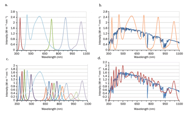
Figure 3. (a) Individual spectra of six LEDs; (b) Comparison between the measured spectrum of six-wavelength LED solar simulator (orange) and standard sunlight at ASTM G-173 AM 1.5 (blue); (c) Individual spectra of 23 LEDs; (d) Comparison between the measured spectrum of 23-wavelength LED solar simulator (red) and standard sunlight at ASTM G-173 AM 1.5 (blue). Image courtesy of ProPhotonix
The number of different wavelengths used in the sun simulator dictates how accurately the LED spectrum matches the sun spectrum. For example, the sun simulator can be matched more accurately using 20 or more wavelengths rather than only four (Figure 3). One advantage of having a large number of individual LED wavelengths in a single system is the ability to simulate different scenarios via adjustment of the wavelength intensities. For example, different times of the day can be replicated, as can the effect of shading on the entire target or parts of the target
under test.
During manufacturing, LEDs even from the same batch will vary in color, flux and forward voltage.2 The differences can be significant, and therefore LEDs are measured and delivered to the market in subclasses or groups called bins. The spectral characteristics of a particular bin of LEDs will have a direct impact on the simulator. For example, if the LEDs in a bin are just at the edge of the specification tolerance, the desired output could be compromised. The effect of different LED bins must be considered and understood. Wavelength selection, quantity, placement and bin characterization are essential to a properly designed sun simulator that meets the required specifications.
Uniform light is critical in a sun simulator; it is achieved through wavelength selection, described above, and a proper optical design. If the light is not uniform, it is more difficult for the system to identify issues in the target, or results for artificial weathering and research experiments can be unreliable. Different optical configurations are possible, depending on the required working distances, target areas and optical intensities. A number of tools – lenses (off-the-shelf or custom), reflectors, mirrors, etc. – can be integrated to achieve the desired uniformity. For example, the lens design needs to be looked at in terms of front and back surface curvature, thickness, aperture size, refractive index, alignment tolerance and scattering effects. The optics must be compatible with the manufacturing process, as well as having sufficient transmission across the required spectrum (especially in the UV range, where absorptions are more common).
As described above, to ensure full light mixing, a minimum number of LEDs per wavelength is required, and they must be distributed properly in the sun simulator. The number of LEDs per wavelength is dependent on the required power of each wavelength and the power specifications available for said LED. Computational modeling of all these factors is required to ensure that the optical design accomplishes the target specifications.< br>
The heart of the sun simulator is the electronic design enabling the system to drive multiple LEDs and wavelengths. LEDs with different wavelengths can operate at different voltages, have different operating efficiencies, heat up differently during operation and degrade differently over time. To produce a uniform intensity output with the correct intensity mix between individual wavelengths across the lifetime of the sun simulator, precise electronic control of each LED or group of LEDs is necessary.
With potentially thousands of LEDs in a system, a single intelligent controller would not be able to balance the electrical currents to the precision required – albeit a cost-effective attempt. Adding an intelligent controller for each LED or group of LEDs can lead to an unacceptable rise in costs and an increase in space required for the electronics. Balancing the amount of intelligent control in the system against the available footprint and cost constraints is a key challenge in any sun-simulator design. Optimum hardware and software design is required for the implementation of complex requirements demanded by the target sun-simulator specification.
As discussed earlier, the performance of the LEDs changes over their lifetime, and each wavelength has its own unique lifetime characteristics. A reliable and robust feedback and calibration solution is critical to properly drive the LEDS to maximize lifetime across all LEDs in a system. Feedback mechanisms based on electrical and optical methodologies must be employed to achieve the desired intensity output. Photodiode-based feedback is one such methodology and requires the development of a carefully designed calibration protocol. The electronic design, coupled with properly designed software, is an essential aspect of the overall system design in order to meet the required specifications.
Cost and cost benefit
Only a limited set of LED wavelengths exists, and each wavelength has a limited set of power levels available. The best combination of wavelengths and the number of LEDs for each must be optimized based on the performance specification and the target budget cost. Designing systems requiring precise control of hundreds or thousands of LEDs requires multiple LED drivers and complex software structures. If not optimally designed, the electronics can increase the system costs significantly. Finally, it is important to note that the best solution should take into account not only the up-front costs of the system, but also the lifetime costs in comparison to alternative solutions and the measured impact on the business or research.
Compared with traditional lamp systems, LED systems offer significant benefits over the life of the simulator. Operating costs will be lower due to instant-on/off. Maintenance costs will be lower because of the extended life of LEDs. Heavy metal disposal is eliminated, because LEDs do not suffer this problem. Operating efficiency or research results are improved as a result of the unique control capability of light uniformity, speed of flash and precise spectral output.
Meet the author
Ken Reynolds is business and technology manager at ProPhotonix in Cork, Ireland; email: [email protected].
References
1. G. Cherucheril et al (2011). Multi-junction Solar Cells. EE 332: http://georgecherucheril.weebly.com/uploads/9/8/3/0/9830510/332_paper-final_draft-cherucheril_march_verma.pdf.
2. Philips Lighting Co. LED lamps: LED binning. http://www.lighting.philips.com/pwc_li/main/connect/Lighting_University/internet-courses/LEDs/led-lamps6.html.
3. Solar Junction. Technology: http://www.sj-solar.com/technology/