James Fisher, Newport Corporation
As a supplier of vibration control
equipment, we at Newport are frequently asked if vibration control is really necessary
for microscopy applications, and you might expect the answer to be “of course.”
However, the correct response is slightly more complex because the need for vibration
control lies between the environmental conditions in the laboratory and the requirements
of the experiment.
The lab environment
Identifying and quantifying the potential noise sources in your
lab are the first steps toward understanding what vibration control solutions may
be required to achieve acceptable results.
Most laboratories will contain some nominal level of floor vibration
due to automotive traffic, building sway or large machinery such as elevators, HVAC
equipment or pumps. The magnitude of these disturbances is usually proportional
to their proximity, the type of building construction and their location within
the building. Laboratories located on lower levels or, better yet, in basements
typically will experience lower levels of vibration compared with upper levels of
that same building. A common practice to understand potential vibration problems
is to conduct a vibration site survey to quantify the levels of vibration.
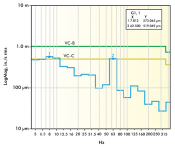
Figure 1. This graph shows vibration data from a VC-B level lab that
generally would be considered above average. Images courtesy of Newport Corp.
Figures 1 and 2 represent vibration site survey data for two different
laboratories. The lab in Figure 1 was located on the second floor of a concrete
structure and is shown to have approximately 58-dB noise at 7.8 and 62 Hz, a combination
of building resonance and rotating equipment. The lab in Figure 2 experiences significantly
lower levels of vibration overall (VC-E), but you can still see signature peaks
at 4.9, 8, 31.5, 60 and 250 Hz. The lower frequencies are typical of building resonances,
while the higher frequencies are typical of rotating equipment. In each of these
locations, the site survey data should be compared to vibration standard criteria
to assess whether the measured and anticipated vibration levels would allow imaging
to the desired resolution.
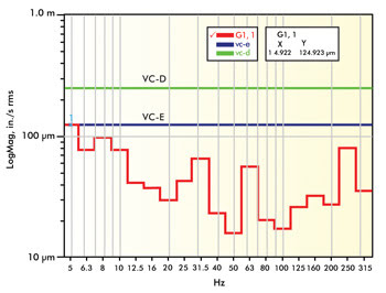
Figure 2. This graph shows vibration
data from a VC-E level lab that generally would be considered exceptional.
For years, the vibration criteria curve, like the one shown in
Figure 3, has been used to perform this assessment. Each curve along the graph represents
maximum vibration levels in terms of both decibel and velocity. Also shown with
each curve is the minimal detail size that could be imaged at each level. For instance,
the lab in Figure 1 had a maximum level of 58 dB at 7.8 and 62 Hz, which puts it
at a VC-B environment. At this level, the minimum feature size you could expect
to image is 3 µm, and optical microscopes could achieve a 1000x magnification with
acceptable image quality. If this research group’s application required imaging
details below 3 µm – let’s say to 0.3 µm – they would certainly
need to incorporate some vibration isolation products that would reduce this noise
level by at least 12 dB (VC-B to VC-D).
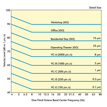
Figure 3. Shown are vibration criteria curves.
However, vibration disturbances can sometimes be sporadic events
that may not occur during site surveys. Consider occasional deliveries of new equipment
or supplies, or an air compressor that would operate only when the main pressure
tank reaches a specified level. In both instances, the generated vibrations may
disturb imaging system results that may have been undetected by a previous vibration
site survey. It is important to consider the measured vibrations and to anticipate
additional sources that may affect imaging results in the future.
Experimental setup
Consider the requirements for coherent anti-Stokes Raman scattering
(CARS) microscopy. CARS was first reported in 1965 by Maker and Terhune1 as a method
of spectroscopy for chemical analysis. CARS as a method of microscopy was first
reported in 19822 and later revisited by the Xie group in 1999.3 Being a nonlinear
process, it allows image sectioning similar to two-photon excited fluorescence microscopy
without the need for sample labeling.

Figure 4. (Left) A
CARS microspectrometer system illustrates the long beam paths that can be sensitive
to platform vibrations. The slightest deviations in path length or spatial alignment
will cause image degradation. (Right) A CARS image of bovine muscle taken at Newport’s
Technology and Applications Center Lab in Irvine, Calif.
An experimental setup of a CARS spectrometer system from Newport’s
Technology Applications Center is shown in Figure 4. The most challenging part of
constructing a CARS setup is correct timing between the pump and Stokes pulses,
as they must overlap in both time and space. This requires not only precision components
to execute but also a stable platform to maintain the temporal and spatial distances
during imaging. Relative changes of the optical path length between pump and Stokes
beam by tens of microns, or spatial misalignment of the two beams, leads to significant
degradation of the anti-Stokes signal. A typical CARS imaging system provides a
resolution down to 500 nm, so even the smallest amount of platform vibration could
dramatically affect image quality. To reach this level of performance, the laboratory
environment would need to be at a VC-D level, which is better than typical research
labs, or incorporate both pneumatic isolation and damped optical surfaces.
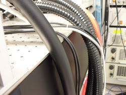
Figure 5. Tight hoses hanging
off platforms like those shown can transmit vibrations directly onto the table surface.
These cables should have some type of foam isolator placed under them or be supported
so they do not touch the table.
In addition to understanding the lab environment and experimental
needs, users also must be aware of system design and construction issues that would
also affect imaging results. One common issue seen with microscopy vibration problems
occurs when users accidentally couple floor vibrations directly into their table
via rigid hoses or rotating devices, or when systems are installed under air ducts.
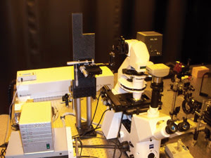
Figure 6. The use of a
dual damped rod structure improves image quality by reducing unwanted vibrations.
The use of undamped posts or poorly constructed vertical supports is a common cause
of image degradation.
In any lab environment, the most effective and economical method
of vibration control is eliminating the vibration source. Asking a facilities team
to move a noisy pump room is probably a little too extreme, but making sure that
no unnecessary sources of vibration are being introduced into the table surface
is much more manageable and economical. This includes isolating rigid compressor
or pump hoses from the table surface through the use of service loops or soft foam
(Figure 5). Also, minimizing the height of beam steering paths or assuring that
they are sufficiently rigid or damped will help improve image quality (Figure 6).
Air ducts are another common problem, since they can induce both mechanical motion
and thermal changes that would affect image quality (Figure 7). Wherever possible,
systems should not be located in the path of supply ducts, and ducts should be baffled
if possible so that airflow is not directed into the system.
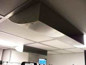
Figure 7. Air duct baffles redirect airflow and will help reduce
tabletop disturbances while maintaining proper lab temperatures.
Vibration control solutions
Any vibration control system essentially has two goals. The first
is to effectively reduce the impact of environmental noise to a level that will
maintain an acceptable relative spatial position of the elements within your system.
Examples of this include building vibrations transmitted through the floor that
can affect laser beam stability, optical element positioning and target point stability.
This is traditionally provided by vibration isolation products such as pneumatic
or elastomeric isolators – Newport’s S-2000 stabilizer isolator or its
NewDamp elastomer isolators, for example.
The second goal is to protect system components from being excited
by external sources within the system itself. This includes disturbances residing
atop or around the instrumentation that originate from positioning stages or rotating
devices, cooling fans or pumps. These types of disturbances tend to propagate along
the table surface and excite the natural frequencies of the table or breadboard,
or even the microscope equipment itself. The most effective method at reducing these
disturbances is through the use of rigid platforms that use tuned mass dampers like
those found in Newport RS2000 series tables.
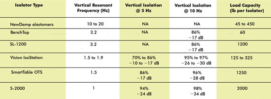
Recall the vibration data shown in Figure 2, where the lab experienced
58 dB of noise at 8 and 62 Hz, and combine that with a need to build a new CARS
setup for in vivo imaging of myelin fibers down to 500 nm. With 58 dB of noise (VC-B)
and a requirement of a 48-dB level (VC-D), this facility would have to incorporate
a vibration control solution capable of providing a 10-dB reduction in transmitted
vibrations at 8 and 62 Hz. The performance data presented in Table 1 illustrates
the various isolator options available, depending upon the performance and load
capacity. At the targeted frequencies, an elastomeric solution would not provide
sufficient reduction, and the performance from an active isolation system would
not be worth the price. However, pneumatic isolators like Newport’s S-2000,
OTS platform or even the SL-1200 would provide sufficient performance for this application.
For microscopy applications with a smaller footprint (less than 3 x 6 ft), users
could even consider a vibration-isolated workstation system like the new Vision
IsoStation (Figure 8).
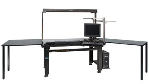
Figure 8. The new Vision IsoStation
is available in multiple sizes from 24 x 24 up to 36 x 72 in. and two load capacities,
500 and 1300 lb. All models reduce transmitted vertical and horizontal vibrations
by 70 percent (-10 dB) or more at 5 Hz and by more than 95 percent (–26 dB) at 10
Hz. The multiple storage and work surface options also help provide areas to store
nonessential items or instrumentation that might otherwise induce vibrations.
In some situations, the lab environment may not be well understood
or may even change over time as new buildings, roads or rooms are added to the campus.
There is also the possibility of entire labs moving to new buildings or floors.
Additionally, experiments may change over time, typically becoming more complex
than originally planned. Because of these ever-changing situations, the best approach
is to focus on near-term needs but also to consider equipment that could be field-upgraded
in the future to improve performance.
Newport’s SmartTable OTS system was designed specifically
to address these needs since the system can be purchased initially as a rigid frame
support and can be field-upgraded to a fully pneumatic, active-leveling isolated
platform (Figure 9). There are also two upgradable table models available with this
system that can also be field-upgraded to a system that is fully, actively damped.
Since most imaging platforms are in service for many years, it is important to select
equipment that will meet today’s requirements but also serve future needs
as they arise.
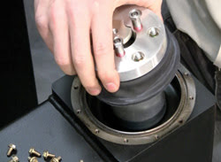
Figure 9. Choosing field-upgradable vibration control solutions like
the SmartTable OTS platform isolator shown here can help meet near-term budgetary
requirements and long-term performance needs.
The vibration control solutions that biological imaging applications
require are similar to those for laser applications, and both should start with
an understanding and quantification of the potential sources of noise. This would
be followed by an assessment of the needs of the system to determine what, if any,
level of vibration reduction is necessary. Finally, constructing the system in a
manner that minimizes noise sources and maintains an organized and quiet work space
will result in many successful investigations and, hopefully, new discoveries.
Meet the author
James Fisher is senior group director for Newport’s Vibration
Control Group; e-mail: [email protected].
References
1. P.D. Maker and R.W. Terhune (February 1965). Study of optical
effects due to an induced polarization third order in the electric field strength.
Phys. Rev., pp. 801-818.
2. M.D. Duncan et al (1982). Scanning coherent anti-Stokes Raman
microscope. Opt. Lett., pp. 350-352.
3. A. Zumbusch et al (May 1999). Three-dimensional vibrational
imaging by coherent anti-Stokes Raman scattering. Phys. Rev. Lett., pp. 4142-4145.