Alfons Zöller, Michael Boos, Harro Hagedorn, Werner Klug and Christopher Schmitt, Leybold Optics GmbH
In situ optical monitoring techniques have been critical components of both plasma-assisted evaporation and magnetron sputtering coating techniques for several years. Until recently, though, it wasn’t uncommon for limitations related to coating thickness accuracy and other factors to cause yield problems. Advances in monitor design based on a grating monochromator and lightguiding have boosted system sensitivity by reducing noise levels and improving signal stability. Added benefits include the ability to monitor intermittent sputtering processes directly.
To understand the impact of these design features, it helps to briefly examine common monitoring strategies, one of which often involves some form of timed control of thickness deposition. This strategy can work well in sputtering processes because they normally feature stable deposition rates as well as stable optical properties such as refractive index. The thickness accuracy, however, is usually limited to roughly 1 to 5 percent, depending on the chamber configuration. There also can be long-term drifts in the deposition rate.
Time control will not work as well for evaporation processes because the deposition rate is not as stable. An alternate method for thickness control is quartz crystal monitoring. In this case, a quartz crystal with an oscillator is deposited along with the substrates. The oscillation frequency of the crystal (4 to 6 MHz) will change with its increased mass as deposition layers are added. The change in frequency is proportional to the film thickness. This method has some drawbacks, though, because it measures only the physical thickness of the film without considering the optical properties.
One solution is to use a single-wavelength optical monitor, such as Leybold Optics GmbH’s OMS 4000, to measure optical properties in situ. The strategy involves measuring the reflectance or transmittance at a selected wavelength. When the data are plotted against growing film thickness, the resulting curve is strongly nonlinear. Extensive software algorithms can calculate the theoretical monitoring curve with precision. A comparison of the calculated and the measured monitor curve during processing can then be used to determine the optical film thickness (refractive index times physical thickness) in situ, in both plasma-assisted evaporation and magnetron sputtering processes.
Monitor design
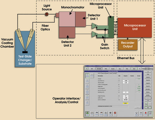
To begin in situ coating measurement, the emission from the light source is coupled into two fiber optic bundles: one for the measuring light and one for the reference light (Figure 1). Light used in measurement is chopped mechanically and transmitted through a measuring fiber bundle to the optical feedthrough of the deposition chamber. The reference bundle guides the light directly through the monochromator to the attached detector, and a lens focuses light transmitted from the exit face of the measuring bundle onto a test glass or witness piece. The reflected or transmitted light from this is then coupled by another lens into a fiber bundle, which transports the measuring light to the entrance slit of the monochromator.

Figure 1. The optical design of the OMS 4000 monitor has extended in situ thin-film monitoring capability to intermittent measurements on a rotating substrate holder. This allows direct monitoring in intermittent sputtering processes and offers an alternative to indirect monitoring of stationary test glasses used with evaporation systems.
The cross sections of fiber bundles can be shaped according to the demands of specific functions. For example, a rectangular cross section is used to recombine the measuring and reference bundles to the entrance slit of the monochromator. The monochromator’s exit and the attached photodetector can be illuminated sequentially by the measuring and reference light followed by a dark phase. Illumination is either with a halogen lamp — the most common choice for visual and near-IR applications — or a deuterium lamp, for UV measurements.
Transmittance properties of the optical fibers also are the key determiners of the spectral range of the optical monitor. Working with as many as two fiber types per bundle, the system designers can cover a wavelength range of 220 to 2300 nm. To isolate the required wavelength for measurement, the system monochromator uses three gratings, as well as blocking filters designed to suppress higher-order wavelengths. Spectral resolution will vary from 0.3 to 10 nm, depending on the grating used and the slit width.
The system also will automatically select up to two detectors out of a possible four to work with, depending on the required monitor wavelength. Detector options include a silicon photodiode (for 400 to 1100 nm), an InGaAs diode (850 to 1700 nm), a PbS photoresistor (1000 to 2300 nm) and a photomultiplier tube (220 to 650 nm).
The feedback loop between the detectors and coating chamber is another key component to ensuring real-time deposition monitoring. Once a detector transforms the light variations between the reference and measuring beams into electrical signals, the signals are amplified and digitized by a high-resolution analog-to-digital converter. A microcontroller sends information through a serial interface to an industrial PC that processes feedback. Total dynamic range for this setup is 26 bits.
System capabilities are further expanded by the light chopping design, which supports accurate monitoring of coating deposition on stationary test slides as well as direct monitoring on rotating substrate holders in intermittent mode using a chopper frequency variable from 10 to 80 Hz.
The PC software can support monochromatic monitoring of both simple and complex optical layer systems. The relevant layer parameters, including refractive index, optical thickness and monitoring wavelength, are transmitted from the coating chamber control via Ethernet. Real-time communications such as source shutter control are performed with digital signals.
Before layer deposition begins, the OMS 4000 will analyze the theoretical monitoring curve produced with the PC software and then determine cutoff criteria and necessary photometric parameters, such as amplifier gain and the optimum time constant for the signal processing. Depending on the monitoring strategy, engineers can program the system to use turning-point or trigger-point monitoring, with online correction of the latter done with extensive software algorithms as shown in Figure 1. This feedback strategy makes it possible to monitor nonquarter-wave stacks on a stationary single test glass, or on a witness piece on the rotating substrate holder in case of direct monitoring.
With optional software functionality, end users can conduct spectral scans to determine any vacuum-to-air shift, which would be done by measuring spectral reflectance or transmittance in vacuum and after venting. Scanning also can be used to analyze spectra after individual layers are deposited.
So far, engineers have used the in situ coating monitor for standard applications in the UV, VIS and NIR spectral regions. In a UV coating process (v-coating at 248 nm), for example, they achieved a run-to-run reproducibility of ±0.3 percent on a planetary substrate holder.
Indirect monitoring tests also were run on color filters in a standard Leybold Syruspro 1100 coating chamber using a 1000-mm-diameter dome-shaped substrate holder with single rotation. Results included shift-free stable layer systems during plasma-ion-assisted deposition with an Advanced Plasma source.1
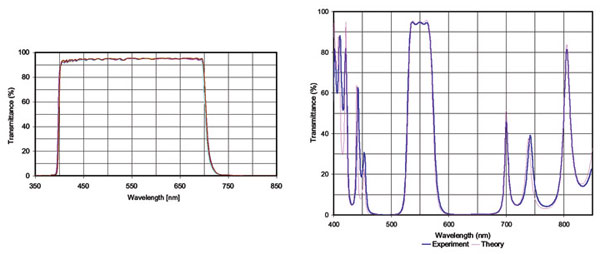
The scientists produced color filters with alternating layers of SiO2 and a high-index oxide material and investigated reproducibility of an IR-cut filter (Figure 2). During indirect monitoring with different stationary test slides, they could select monitoring wavelengths in such a way that the layers terminated at online corrected trigger points. For six consecutive runs, the wavelengths of the 50 percent transmittance point for the short- and long-wave edges were in the range of ±0.15 and ±0.1 percent, respectively. Some calibration and test runs were necessary to determine tooling factors.

Figure 2. Graphs illustrate the comparisons between theory and spectral performance for two cases: (a) six consecutive runs of a UV-IR cut filter, and (b) a five-cavity filter produced with direct monitoring.
Another application involved direct monitoring of bandpass filters on a rotating substrate holder in a Helios magnetron sputtering system.2 The optical monitor was synchronized with the substrate holder, which rotated at about 200 rpm. One representative witness piece, placed roughly 300 mm off-center, also was measured intermittently.
An expected benefit of direct monitoring is higher yield, especially in magnetron sputtering systems, because calibration runs can be avoided. Nor do tooling variations adversely affect yield on substrates placed on the same radius as the witness piece. Further research will examine direct monitoring in more detail for plasma-ion-assisted deposition and magnetron sputtering, especially direct monitoring of nonquarter-wave stacks
Meet the authors
Alfons Zöller, Michael Boos, Harro Hagedorn, Werner Klug and Christopher Schmitt are researchers in the optical coating technology group of Leybold Optics GmbH in Alzenau, Germany; e-mail: [email protected].
References
1. A. Zöller et al (1997). Plasma-ion-assisted deposition: a powerful technology for the production of optical coatings. Proc. SPIE, Vol. 3133-23.
2. M. Scherer, J. Pistner and W. Lehnert (2004). SVC 47th annual conf. proceedings, paper HGP-1.