Combining steps on one machine enables precision production of free-form optics.
Michael Thomas and Dr. Michael Sander, Satisloh GmbH
Production of free-form optics is one of the most challenging areas in the precision optics industry, creating continuously increasing demands on the machine manufacturers. Free-form optics include rotationally symmetric parts, such as aspheres and parabolic mirrors, which are common components in state-of-the-art optical instruments. Significantly greater challenges are presented by nonrotationally symmetric parts, such as complex beam-shaping elements or off-axis head-up display mirrors.
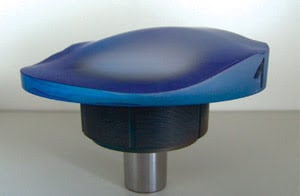
Figure 1. Nonrotationally symmetric optical free-form optics (surface shown here) are particularly difficult to manufacture.
A unique seven-axis polishing solution combining pre- or fine-polishing with corrective polishing down to accuracies of better than λ/10 significantly advances optical free-form production technology.
Producing optics
To make these optics, computer-aided-design (CAD) data describing the free form is transferred to computer numerical control (CNC) machine code for the generation or grinding. Simulation of the complex generating process ensures safe production, followed by metrology and polishing, which are done in iterations until the desired surface quality and shape accuracy are reached. Precise absolute measurements — a critical step — are performed by profilometry, 3-D measurement or computer-generated-hologram/interferometry.
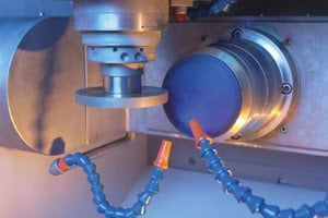
The disk tool can perform pre- and fine-grinding of free-form shapes.
Generating the free-form shape is a well-established process that is performed using cup-wheel or disk-shaped bonded diamond tools with a suitable grid (facing page). A tool changer enables complex creation of free-form shapes. Proper selection of the cutting speed results in optimum process times and minimizes tool wear.
Achieving accuracy
Minimizing tool wear is important for achieving a highly accurate free-form shape. The degree of wear depends on the bonding material used, on the concentration of diamond, on processing parameters such as feed rate, removal rate and revolution speed of the workpiece, and on tool spindle. If the parameters are well-balanced to the probe properties, tool wear can be lessened and surface accuracy maintained. Form accuracies of <1.5 μm peak to valley and surface roughness of Ra ≤0.035 μm can be achieved by using the new technology.
Polishing of free-form optics traditionally has required use of a separate machine for the generic process for the ground substrate and for figure correction or corrective polishing. Each involves a different polishing process. Conventional polishing is done with slurry, and the others are done via magneto-rheological finishing or ion-beam figuring.
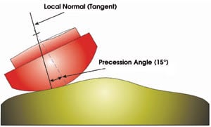
Figure 2. Adjusting the precession angle allows precise control of the polishing rate.
The seven-axis technology of Satisloh GmbH’s A-I and A-II polishing robots combines fast polishing and dedicated deterministic corrective polishing. It has a finely tunable polishing rate, which is essential for performing the steps from the fast pre- and fine-polishing of the ground surface to the very low rates used during corrective polishing (Figure 2). The complete process cell can be covered by one polisher plus the generator and the link to metrology equipment, and it can achieve accuracy of better than λ/10, as verified on aspheres.
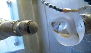
Figure 3. The polishing tool is dome-shaped, and its elasticity can be adjusted.
The polishing tool used is a half dome with an elasticity that is adjusted by changing pressurized air from the back (Figure 3). The software’s influence function is first determined using an automated procedure, which generates a reusable set of parameters for various spot sizes and polishing rates (Figure 4).
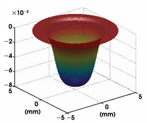
Figure 4. The influence function generatesparameters for various spot sizes.
The influence function is important because it forms the basis of the calculation of the tool path according to the removal rate. The function contains all necessary variables, such as density of polishing slurry, roughness of the polishing pad, pressure of the polishing tool, revolution speed of the workpiece and polishing tool, as well as the precession angle.
In a manner similar to the data transfer of a CAD file to the generator for grinding, an error map is transferred from metrology to the precessions software. With the influence function, actual profile and design profile, the 3-D Precessions software developed by Zeeko Ltd. of Coalville, UK, calculates the tool path and the dwell time to correct the free-form surface (Figure 5).
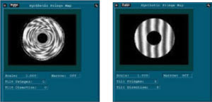
Figure 5. Software performs final corrections on the optics, as seen before (left) and after correction (right).
Depending on the shape and curvature of the optics, deterministic material removal during polishing can be achieved in spiral-, raster-and random-mode tool paths. The option to vary spot size and influence function during the process makes this an extremely powerful method.
Although the precession angle of the tool is relevant for the removal rate, variation of the angle during polishing creates a randomizing effect on the surface structure, realizing elimination of mid-spatial frequencies. This polishing technology has been successfully applied not only to small optics, but also to components of >2 m.
Meet the author
Michael Thomas is international sales manager and Michael Sander is head of precision optics at Satisloh GmbH in Wetzlar, Germany; e-mail: [email protected].