BILL SILVER, COGNEX CORP.
Traditionally, 1D barcodes have been read by laser scanners that project a beam across the barcode and use reflected light to generate an electrical signal for decoding. Although these scanners are mature and effective, a number of inherent disadvantages have motivated a switch to image-based readers using 2D sensors.
Image-based readers promise higher read rates. They are able to read 2D codes and handle a wide variety of materials and printing methods. And they have no moving parts. But the readers’ promise has been hard to deliver in practice because of the challenges to capturing quality images and analyzing those images with sufficient fidelity and speed. A new method is available that can locate codes in an image and extract high-fidelity signals at remarkable speeds. It does so by explicitly modeling the behavior of fine features on a pixel grid, using algorithms matched to contemporary processor architecture.

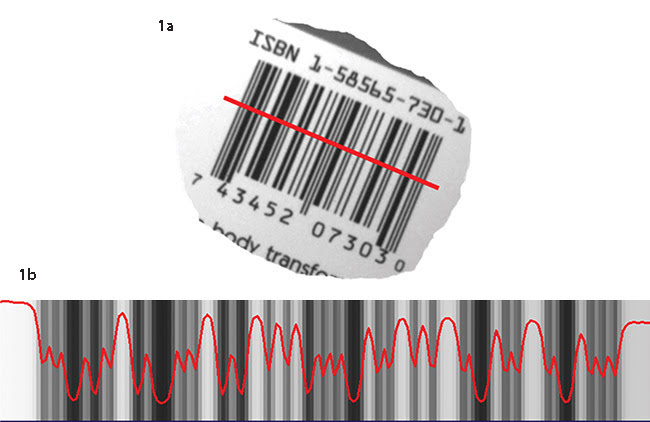
Figure 1. A barcode imaged at 1.5 PPM (a). A 1D signal will be extracted along the red projection line for decoding. In an example of bilinear interpolation, the bars and spaces in the 2D barcode have been successfully reproduced in a 1D signal (b). Courtesy of Cognex Corp.
Laser scanners, on the other hand, project a beam through a rotating prism that directs it onto the barcode. Sensors capture the intensity of reflected light to produce a signal that can be decoded. Laser scanners are effective in high-contrast applications, providing excellent performance for high-speed unidirectional scanning and offering large depth of field and a simple setup.
This scanning method has several limitations. Seeing only one scan line at a time, laser scanners perform poorly when codes don’t appear as expected by the specification. Laser scanners cannot read 2D codes, which are increasingly used in consumer and industrial applications ranging from aerospace and automotive to food and pharmaceuticals. Finally, laser scanners use moving parts that wear out and can easily be damaged from shock or vibration.
Image-based code reading generally involves four steps:
• Capture an image that is in focus and of sufficient resolution.
• Locate codes regardless of size and orientation.
• Extract 1D signals along the located codes.
• Decode those signals.
These steps must be fast enough to keep pace with contemporary logistics and manufacturing processes.
High-speed, automatic focus
Laser beams project spots that are bright and easy to focus, while image capture requires light and focus over a wide area. But newer technology has made image capture competitive. Cognex, for example, offers ID readers that use ultrabright LEDs and liquid lenses that can automatically focus at high speeds.
With an image of the entire code available, rather than just one or two scans, sophisticated decoding algorithms can handle degradations in code quality caused by damage, reflections, quiet zone violations, and differences in material types and surfaces. The algorithms enable image-based readers to successfully read codes of widely varying code quality, size, marking method or material. They can accommodate print variations (color, poor print, scratched, washed out), as well as various printing (ink jet, dot peen, laser etch, direct part mark) and surface (glass, metal, cardboard, ceramic, plastic) types.
Image-based ID readers can also read 2D codes such as data matrix that hold a much larger volume of data, providing redundancy that can enable the code to be read even when it is damaged. An image-based barcode reader is able to interpret multiple barcodes in any orientation within a single view. With no moving parts, their normal life is considerably longer than laser scanners.
Sophisticated image capture and decoding algorithms are not sufficient, however. The other two steps — locating codes and extracting signals — have long relied on methods that couldn’t compete with the speed and resolution of a laser scan. The great advantage of a 2D image — a complete picture of the code — comes at a price, as there is much more information to process in the same amount of time. The quantization of an image into a pixel grid also introduces distortions of fine features that cause loss of fidelity when using those traditional image analysis methods. The dual challenge of speed and fidelity must be overcome if image-based readers are to achieve their promise.
Accuracy and noise reduction
A method for locating codes and extracting signals developed specifically for barcode reading overcomes existing challenges. The principal problem is one of geometry. A pixel grid comprises squares arranged horizontally and vertically, but barcodes can be presented in any orientation. For bars much wider than the size of a pixel, this doesn’t matter much. But if a bar is about the same width as a pixel, it can become nearly invisible in unfavorable positions and orientations when using traditional image analysis methods.
One of the best traditional methods is bilinear interpolation, which models orientation as a rotation in the continuous plane (i.e., not a discrete grid). An image of a barcode is rotated to horizontal by calculating where each pixel of the horizontal code would fall. The calculated location falls in between four neighboring original pixels, and bilinear interpolation calculates a pixel value corresponding to this in-between location. Interpolated values are then averaged vertically to reduce noise.
Bilinear interpolation offers great geometric accuracy (i.e., it doesn’t distort size and spacing), but it introduces significant and uncontrollable blur and is relatively slow because there are many computations to perform.
The new method begins with an analysis of the pixel grid’s effect on orientation at each approximately one-degree step from horizontal to vertical. For each step, a plan is created for analyzing that specific orientation. The plan has two parts: how to process neighboring pixels to control blur and reduce noise, and how to use the architecture of contemporary processors to achieve high speed. These plans are then used in the barcode reading process to achieve fidelity and speed.
A barcode is imaged at a resolution of 1.5 pixels per module or PPM (a module is the smallest bar or space) and a projection line is generated in red, along which a 1D signal is to be extracted for a decode attempt (Figure 1a). Bilinear interpolation creates a 1D signal in which all of the bars and spaces present in the 2D image have been faithfully reproduced, and a successful decode is assured (Figure 1b).

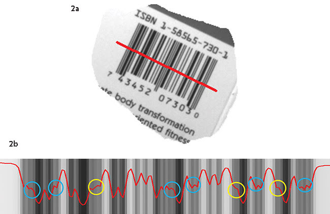
Figure 2. A barcode imaged at a lower resolution (1.2 PPM) enables a wider field of view (a). Bilinear interpolation has been unable to resolve some of the barcode’s finer features (b). As seen in the 1D signal, the six bars and spaces shown with blue circles are extremely attenuated, while those shown with yellow circles are entirely lost. Courtesy of Cognex Corp.
Imaging the same barcode at a lower resolution of 1.2 PPM enables a wider field of view (Figure 2a). But in this case, the 1D signal resulting from bilinear interpolation cannot resolve many of the finer features (Figure 2b). Six bars and spaces, shown with blue circles, are severely attenuated, and three, shown with yellow circles, are completely lost. The 1D signal at 1.2 PPM cannot be decoded using bilinear interpolation.
On the other hand, a 1D signal extracted from the same 1.2 PPM image along the same projection line, but using the new Hotbars image analysis technology doesn’t have any severely attenuated or lost features, so the barcode can easily be read (Figure 3). Hotbars achieves the same geometric accuracy and noise reduction, while introducing substantially less blur, at speeds typically 20 times faster than bilinear interpolation. The spectacular difference in fidelity and speed is due entirely to the method used for processing the source image.

Figure 3. The 1D signal extracted from the 1.2-PPM image via Hotbars shows no loss of features. Courtesy of Cognex Corp.
An example of how this analysis technology can improve real-world barcode reading performance is provided by an application involving reading codes on process-free printing plates. These plates reduce costs for high-volume printers by eliminating the need to maintain and run a processor and reducing the need for chemicals, water and energy. But the plates create a major challenge for the automated lines that sort and transport the large number of plates used by major printers.
Plate lines read codes at multiple points to identify plates so they can be transported to the proper location. While the codes on conventional plates are clearly visible to the naked eye and relatively easy to read, codes on process-free plates are invisible and much harder to read. Engineers at NELA, the world’s leading producer of plate lines, found that the laser scanner code readers used in the past were unable to read the codes on process-free plates, even in infrared light. They tried other code readers and found that the Cognex DataMan 300 image-based ID reader using Hotbars image analysis technology is able to provide near 100 percent read rates.
Meet the author
Bill Silver is senior vice president and senior fellow at Cognex Corp. in Natick, Mass.; email: [email protected].