Extended area blackbodies are now commonly used as reference sources for IR cameras, simultaneously calibrated. The uniformity of the reference blackbody is therefore essential. A newly developed specific bench measures IR source uniformity with a high accuracy.
CATHERINE BARRAT, HGH INFRARED SYSTEMS INC.
To increase productivity, more and more IR camera manufacturers are developing parallel calibration processes, in which a set of sensors are facing a reference source consisting of a large area blackbody. Consequently, demanding constraints are reported on the specification of the reference source — the thermal radiation of each point of the emissive surface of the large area blackbody must be accurately monitored.
For example, let’s consider the mass production of IR sensors for smartphones and human body temperature sensors. Typical configuration is 8/9 IR sensors simultaneously calibrated using a 180 × 180 mm2 blackbody. The maximum required difference of calibration from one sensor to another is 0.1 °C at 42 °C. This specification is directly transferred to the nonuniformity specification for the infrared reference source.
Therefore, blackbody manufacturers had to develop new methods for measuring the uniformity of blackbodies and, if necessary, improving their manufacturing process.
Blackbody uniformity measurement
The first idea when measuring the uniformity of an infrared source is to use a thermal imager. The recent advances in technology over the past 10 years bring confidence in the performances of these imagers for quantitative applications. However, considering the results of a recent study, the use of IR cameras for uniformity measurement of an IR reference source must be strictly limited to an approach of the nonuniformity value, such as for the diagnostics of heater failure. This is mainly due to two factors:
• The intrinsic nonuniformity of the camera. A 2014 study published in Quantitative InfraRed Thermography Journal1 shows that the thermal imagers deliver thermal maps with an intrinsic nonuniformity of about 1 to 1.5 percent of the temperature of the measured source. This level of error is at least the same as the nonuniformity level requirement for high-end application blackbodies. So using thermal imagers as testing tools for infrared reference sources’ uniformity must be limited to a resistance failure diagnostic.
• The size of source effect (SSE). The SSE is the ratio between the signal delivered by a camera aiming at a small centered source and the signal delivered by the camera over the same centered point while aiming at an extended area source at the same temperature. The difference between the two measurements is usually due to parasitic radiation entering the aperture of the camera and creating diffractions, scatters and reflections into internal optics (Figure 1).
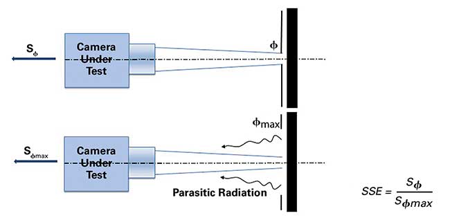
Figure 1. SSE measurement procedure. Courtesy of HGH Infrared Systems Inc.
The study shows that this ratio may get up to 1.10 at low temperature (down to −10 °C) for an extended source of 70 mm, compared to a small source of less than 10 mm. These conditions are equivalent to a temperature difference of 5 °C. Using a thermal imager to measure the nonuniformity of a low-temperature extended area source (by reading only the central point measurement through the scanning method) may lead to several degrees of fake nonuniformity between the edges and the center of the source under test. Similar unsatisfying results are obtained for high temperatures (SSE lower than 0.9).
Uniformity measurement tool integration
A uniformity measurement tool is the key element of the blackbody testing bench named B3, developed by HGH Infrared Systems. This tool is made by the combination of a single element radiometer mounted on a motorized XY translation assembly (Figure 2).
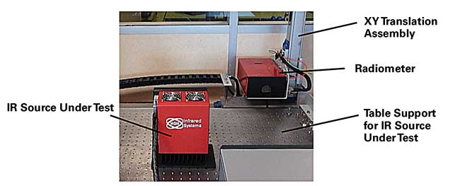
Figure 2. Overview of the IR sources uniformity measurement bench. Courtesy of HGH Infrared Systems Inc.
The uniformity measurement procedure is achieved by scanning the emissive surface of the IR reference source under test. The radiometric signal can then be acquired from the radiometer (Figure 3) — made by a single element detector cooled by thermoelectric elements — while also controlling its position through the XY assembly. The optics focuses the emissive plane of the IR source on the detector sensitive plane; the testing distance between the radiometer and IR source is about 0.3 m.
An intermediate focusing plane defines the position of an aperture hole. A filter holder is located close to this intermediate focusing plane. Here, neutral filters are inserted to adapt the signal level of high temperature sources to the sensitive range of the detector.
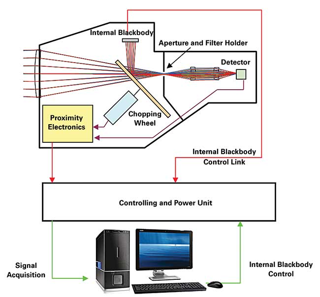
Figure 3. Operating sketch of the radiometer. Courtesy of HGH Infrared Systems Inc.
As the single element detector is not sensitive to a continuous signal, a chopping wheel modulates the radiometric indicator. This chopping wheel also reflects the radiation of an internal blackbody. Consequently, the radiometer signal is proportional to the difference between the radiant flux emitted by the source being tested and the radiant flux that is emitted by the internal blackbody, the temperature of which is measured in real time by the software.
The temperature of the internal blackbody may be adjusted to match the average signal delivered by the source under test. This procedure increases the dynamic range of measurement in order to improve the thermal resolution on small temperature changes of the source. This function is particularly dedicated to the test of low-temperature blackbodies.
The radiometer signal is also calibrated using a reference blackbody model that is linked to International Primary Standards before each campaign of measurements. The model depends on the temperature range used for the radiometer. In a case of high-temperature range, the radiometer (including its appropriate neutral density) is calibrated using a high-temperature cavity reference blackbody.
Scanning method
Thanks to the XY translation stages, the radiometer successively delivers the radiometric temperature of different points of the emissive surface of the IR source under test. An optimized network is consequently defined depending on the dimension of the source’s emissive area. For example:
• For a 25-mm diameter cavity blackbody, there is a network of 11 × 11 measurement points, with a step of 2.5 mm.
This network takes into account the dimensions of the radiometer spot into the source aperture plane, i.e., 5 mm. To avoid an edge effect, the edges’ measurements are removed from the uniformity calculation (Figure 4).
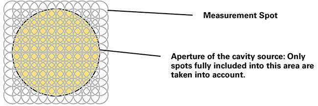
Figure 4. Courtesy of HGH Infrared Systems Inc.
• For a 180 × 180-mm extended area source, there is a network of 11 × 11 measurement points, with a step of 15.5 mm. The spots at the edges are fully included in the emissive surface area. Hence, all the spots are considered for uniformity calculation. The approximate duration of the measurement procedure is 10 minutes; a tighter network increases the duration of the procedure in an approximate proportion with the number of measured spots (in Figure 4, 121 total points of measurement, regularly spaced over the emissive area).
Temporal drift correction
Two measurements of the same point of a source, which are stable over time, allow evaluation of the temporal drift of the radiometer. A maximum drift of 0.04 °C at 85 °C is measured over 2 minutes. This drift cannot be considered negligible compared to the expected uniformity of extended-area low-temperature blackbodies (0.1 °C at 50 °C) (Figure 5).

Figure 5. Correction procedure of the temporal drift of the radiometer. Courtesy of HGH Infrared Systems Inc.
Consequently, the raw measurements are corrected by removing the drift of the radiometer, measured in real time. A point of the source is defined as the reference point for the drift measurement. The temperature Tref(t0) of the reference point is measured at the beginning of the scanning process. At the end of each complete measured column (c), the radiometer gets back to the reference point and measures the temperature of the reference point Tref(c). The drift of raw measurements of the spots of the column is removed in proportion of the time elapsed since t0.
Performances and test results
The SSE of the radiometer has been measured according to the procedure shown in Figure 1 for different temperatures; the measured SSE of the radiometer, at any temperature, is about 0.999. This level leads to an error of 30 mK at 50 °C.
The noise level of the radiometer must have a limited contribution to the uniformity measurement error. The NETD (noise equivalent temperature difference) of the radiometer has been measured especially at low temperatures. The noise level is measured over 100 samples, i.e., signal acquisition considering the modulation frequency of the chopping wheel. This averaging condition is applied to all further measurements, especially to the temperature measurement of each spot during the uniformity test. The measured NETD level of the radiometer is then 10 mK at 50 °C.
The global error of uniformity measurement is evaluated at 50 °C over a 50 × 50 mm2 low-temperature blackbody. This source is assumed to be uniform, as it is equipped with only one heating/cooling device wider than the emissive surface area, and subsequently has no edge effect; the air convection effect is evaluated at 15 mK over such a small height (50 mm). A thermal map of this source is acquired using the B3 bench and the rms (root mean square) uniformity is calculated (Figure 6). The calculation from the thermal map gives 40 mK. Taking the residual air convection effect into account, we can consider that the error of the uniformity measurement system of the B3 bench is 30 mK rms at 50 °C. This level of error is acceptable considering the residual nonuniformity requirement on low-temperature extended-area blackbodies.
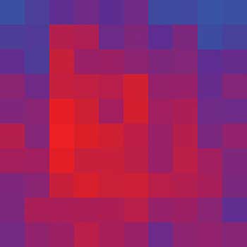
Figure 6. Uniformity thermal map of a 50 × 50-mm2 blackbody (dark blue = 49.255 °C; hot red = 49.464 °C). Courtesy of HGH Infrared Systems Inc.
Examples and analysis: extended area blackbody
The uniformity measurement is conducted on a low temperature IR reference source with a 180 × 180 mm2 emissive surface at 50 °C. The uniformity thermal map is shown in Figure 7. A smoothing algorithm is applied to the image to get a real rendering (Figure 8).
The measured uniformity is 70 mK rms. Though the source is stabilized (2 mK), the residual edges effect of the thermoelectric devices appears clearly on the smoothed image. The air convection effect is also particularly visible in both images. It can be removed by calculating the average of the map in Figure 6 and the thermal uniformity map of the same source turned upside down, taking care to rotate this latter image before the calculation of the average. This method allows getting the thermal map of any IR source when it is used horizontally.
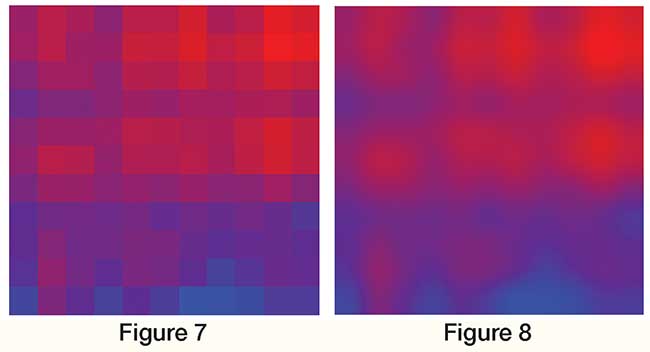
Figure 7 & 8. Uniformity thermal map of a 180 × 180 mm2 blackbody (dark blue = 48.927 °C; hot red = 49.311 °C). Courtesy of HGH Infrared Systems Inc. Courtesy of HGH Infrared Systems Inc.
Measuring the uniformity of IR reference sources such as blackbodies is a challenging operation since they are themselves used for correcting nonuniformity of thermal imagers and IR cameras. As the residual nonuniformity level is higher than expected on blackbodies, the use of such imagers for uniformity measurement must be limited to heaters’/coolers’ failure diagnostic. A high accuracy measurement of the uniformity can be achieved thanks to HGH’s B3 bench. With a maximum error of 30 mK rms at 50 °C, this bench is able to provide the thermal uniformity map of low-temperature, extended-area blackbodies and high-temperature cavity blackbodies, as well. This accurate measurement improves the manufacturing process of high-end blackbodies to make them compatible with the increasing demanding uniformity specifications on these IR reference sources.
Meet the author
Catherine Barrat is manager of the test & measurement product line at HGH Infrared Systems Inc.; email: [email protected].
References
1. A. Whittam et al. (2014) Performance tests of thermal imaging systems to assess their suitability for quantitative temperature measurements. Quant Infrared Thermogr J, QIRT-2014-202.