Determining the fatigue limit of real structures under real operating conditions saves time.
Pierre Bremond, Cedip Infrared Systems
Testing the damage induced by fatigue loading to mechanical structures has traditionally been a challenge because it requires a number of samples and many mechanical tests to obtain an accurate figure of the damage mechanisms and their values. Using infrared cameras with a new twist, Cedip Infrared Systems has implemented a technology that can quickly assess the fatigue limit of most materials.
Called the dissipation mode, or D-Mode, the technique measures the mechanical energy used to damage the inner sample by creating microcracks or dislocation motion, which then dissipates into heat. With this method, fewer samples are required to obtain an accurate value of the fatigue limit. In addition, it can be used on real structures operating in real conditions, as opposed to using a large number of test specimens, as is commonly required by conventional methods.

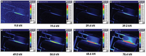
Figure 1. These images of the dissipated energy signal, measured at the surface of a crankshaft, were obtained for several loading levels.
The company’s Altair LI imaging system has been installed on a production line to sample the quality level of an iron crankshaft. The test station automatically measures random samples by plotting the D-Mode signal vs. the applied load. Samples are removed from the production line and manually installed in the test bench, which produces mechanical cycling by applying several loading conditions. This induces stress values into the sample.
The fatigue limit
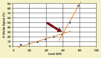
The resulting curve shows a linear increase of the dissipation signal up to the fatigue limit and, after reaching this limit, a rapid increase.
It is clear that the damage has occurred in an area that corresponds to a highly stressed region (Figure 1). When plotting the measured D-Mode signal vs. the load level, the fatigue limit is clearly identified at the breakup point of the signal (Figure 2). In this case, the load level was kept so that the part would never reach the nonelastic domain.

Figure 2. The curve shows the evolution of the D-Mode signal with the increasing loading level. The signal shows a clear break, which corresponds to the fatigue limit of the material.
The manufacturer of these crankshafts relies on the technique to monitor quality on the production line because any discrepancies in the performance of the materials can be detected quickly.
The Altair LI is an advanced imaging software system that uses the Jade mid-infrared focal plane array and that produces noncontact stress images of structures and materials under cyclic loading. The latter device is a standard 320 × 240 high-performance IR camera that produces images with sensitivity less than 20 mK per frame. It connects to a PC via a frame grabber and to the software, which is designed specifically for D-Mode measurement.
The system uses the thermoelasticity principle together with state-of-the-art digital processing electronics that allow the camera to process IR images at speeds up to 200 fps, which reduces the testing time.
The array has a spectral response of 3 to 5 μm with an InSb or mercury-cadmium-telluride detector that produces a resolution of 320 × 256 pixels. The thermal resolution is less than 25 mK of real time per frame.
When a piece of material of any type undergoes cyclic loading, as during fatigue testing, small temperature changes are produced at the material surface. When a solid body is stressed, it gets either hotter, signifying compression, or colder, signifying tension. These changes vary synchronously with loading, and those at the material surface change in phase with the loading. When the cycling stays in the linear domain, the loading induces no plasticity or damage.
The required thermal resolution to achieve a resolution of 1 MPa depends on the material properties. It is determined by the proportionality constant, Km, which corresponds to each material’s stress level, expressed in megapascals, to the induced temperature change.
Meet the author
Pierre Bremond has been in charge of the thermography product line at Cedip Infrared Systems in?Croissy-Beaubourg, France, since 1998.