Rüdiger, Paschotta, RP Photonics Consulting GmbH
Basic knowledge of fiber optics is widespread – but often infected by certain misconceptions.
The basics of fiber optics are seemingly quite simple. Guidance of light in a fiber core can be explained with the physics of total internal reflection, and – at least for step-index fibers – a few simple formulas well describe some essential relations. A closer look, however, often reveals surprising phenomena and shows that some widespread beliefs are not correct. This article presents several examples and shows what really happens in fibers. Numerical simulations are used for these investigations.
The critical reflection angle
One of the most basic elements in the analysis of optical fibers is the critical angle for reflection at the core/cladding interface. Total internal reflection can occur only if light incident on the fiber end propagates with angles against the fiber axis that are below the critical angle, the sine of which is the numerical aperture (NA). So we might expect that the guided fiber modes fully stay within that angular range.
But this is not true, as illustrated with the example of a step-index fiber with a 10-µm core radius and an NA of 0.1. As seen in Figure 1, the angular intensities of the higher-order modes (particularly LP31 and LP12) extend substantially beyond
that limit. Note that the spatial intensity distributions also significantly extend beyond the core/cladding boundary; in that light, the finding may no longer seem so surprising. Also, such effects are less pronounced for fibers with higher NA.
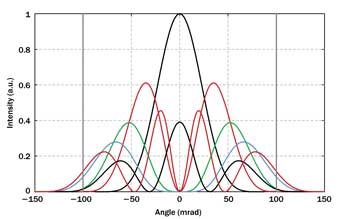
Figure 1. Angular spectra of the modes of a step-index fiber, calculated with spatial Fourier transforms, for 1-µm wavelength. Different colors indicate different l values of the LP modes. The vertical gray bars indicate the critical angle for total internal reflection.
Coupling light into a fiber
It is a common belief that a fiber can essentially guide all light that (a) hits its core and (b) at the same time stays within the angular limits given by the NA. Another example case shows that this is not the full truth. Consider an input wave with a wavelength of 1 µm and the intensity profile of the LP22 mode at 0.85-µm wavelength. (The LP22 mode does not exist at 1 µm.) Much of the intensity profile of that beam is within the fiber core, and Figure 2 shows that this is also true for the angular spectrum. Nevertheless, we can calculate that less than only 1 percent of its power would be guided in the core – in the LP21 mode.
Similarly, a free-space laser beam in a TEM10 mode, well-centered onto a single-mode fiber core, could not be launched at all into the core, even if its size is adjusted such that both in real space and Fourier space the intensity distributions remain largely within the limits given by the fiber. Interestingly, if we cut off one of the two lobes of the input beam with an aperture, or somewhat misalign the beam against the fiber axis, we do get some light into the guided mode.
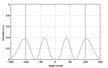
Figure 2. The angular spectrum of an input beam with a 1-µm wavelength and the intensity profile
of the LP22 mode at 0.85-µm wavelength.
These examples show that we also need to consider certain interference phenomena, which are overlooked when considering only plane waves hitting a plane interface. In the case of the TEM10 beam, both lobes contribute some amplitude to the guided LP10 mode of the fiber, but these two amplitudes cancel each other for centered alignment. Even for multimode fibers, certain amplitude distributions that have the “wrong symmetry” cannot efficiently couple into the fiber because of interference effects.
Coupling between fibers
A frequently asked question is how large the power loss for coupling light between two multimode fibers is if their core sizes are not equal. Most people would not expect any losses when the second (output) fiber has a larger core and the NA values of the fibers are identical. After all, the light is essentially coupled into the core of the output fiber only, and its angular spectrum is not changed at the interface. That expectation again turns out to be wrong.
As an example, consider an input fiber with a 10-µm core radius and an NA of 0.1. We now vary the core radius of the output fiber between 0.5 and 2 × 10 µm and calculate the coupling loss at 1-µm wavelength for each mode of the input fiber as a function of the ratio of core sizes (Figure 3).
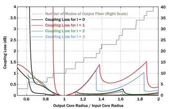
Figure 3. Coupling loss between two fibers as functions of the core size ratio. While the fundamental mode (LP01) exhibits significant losses only if the output fiber has the smaller core, higher-order modes can exhibit substantial coupling losses even if the output fiber has a larger core. Different colors belong to different l values of the modes. Where multiple m values occur, the higher losses belong to the higher m values.
For a too-small output fiber core, the losses get quite high, as we might expect; however, these curves have somewhat strange features, which are associated with changes of the number of guided modes of the output fiber. For some modes, the losses diverge at a certain core diameter, and below that value, no coupling is possible at all.
Surprisingly, for a too-large output fiber core, substantial coupling losses of up to ≈1.5 dB occur for some of the modes, namely for LP12 and LP31.
The overall coupling loss of that fiber joint depends, of course, on the distribution of powers over the modes of the input fiber. This is why we don’t have a simple formula for calculating that coupling loss in case of multimode fibers.
There are also various surprising features for coupling between single-mode fibers. For example, the coupling loss in this case does not depend on the order of the fibers; nonreciprocal behavior is impossible. The coupling loss for any direction of propagation is determined simply by an overlap integral of the two mode functions.
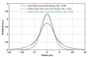
Figure 4. Mode functions of different single-mode fibers. The mode of the output fiber with higher NA fits better to the input mode, if the core radius is drastically reduced.
A particularly surprising case is that of two single-mode fibers with equal core radii of 3 µm but different NA values of 0.08 (input fiber) and 0.12 (output fiber). Although the output fiber is more strongly guiding, its significantly smaller mode leads to a coupling efficiency of only 87.6 percent, corresponding to a coupling loss of 0.575 dB. If, however, we reduce the core size of the second fiber from 3 to 1.5 µm, the mode sizes get more similar (Figure 4), and the coupling efficiency rises to 98.5 percent. So we see that the second version of the output fiber, having a rather small core and a mode that extends far beyond its core, can capture more light from the first fiber.
Coupling loss due to an air gap
Coupling losses also can arise from reflections at fiber ends. Such losses may be particularly disturbing, since reflected light can have undesired effects; a high “return loss” is desirable for some applications.
Some might think that any air gap at a fiber joint is very bad, causing reflections from two air-glass interfaces. However, both reflections may perfectly cancel each other out if the round-trip phase shift in the air gap is an integer multiple of 2π. For example, at 1-µm wavelength, we may have a gap size of 0.5 µm or multiples thereof. For perfect cancellation of the reflection, there is actually a second necessary condition: that beam divergence within the gap is negligible. This, however, is usually no problem for gap sizes of a few microns. Figure 5 shows how the insertion loss and return loss vary with the air gap width.
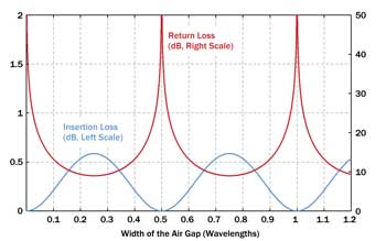
Figure 5. Insertion loss and return loss resulting from an air gap between two fiber ends.
The positions of the loss minima depend on the wavelength, of course. For a limited bandwidth of, for example, a few percent of the average wavelength, combined with a small gap size, this is no problem. A practical issue, however, is to get exactly the right air gap size, which is, of course, easiest for zero gap size – i.e., direct contact of the fiber ends, at least if the fiber ends are cut perpendicularly with a very flat surface. Another solution can be a droplet of index-matching fluid, making the gap size much less critical.
Mode coupling via bending of multimode fibers
If we inject light into only a certain mode of a multimode fiber core, it must stay there – except if we disturb the fiber; e.g., by bending it. We may calculate a modified set of modes for a fiber bent with a certain radius, but for arbitrary evolution of a bend radius along a fiber, it is usually more helpful to numerically simulate the beam propagation.
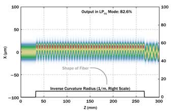
Figure 6. Amplitude distribution in a fiber that is bent with a constant radius in a certain section. The abrupt transitions from straight to bent fiber and back again result in coupling to higher-order modes. The beam propagation was numerically simulated with the RP Fiber Power software.
We consider an example case with a 90° bend of a few-mode fiber with a 20-µm core radius and an NA of 0.05. We launch light only into the fundamental mode (LP01) and simulate how that propagates through the bend. In a first case, we use a constant bend radius of 150 mm in the bent section, as we might expect to be ideal. (For a water pipe, such a bend may work fine.) We see, however, in Figure 6 that the abrupt transition to the bent section causes problems: There are strong oscillations of the field intensity pattern, indicating that a superposition of modes arises. At the fiber end, we have only 82.6 percent of the power left in the LP01 mode, and a still oscillating intensity profile.
We can achieve a nearly adiabatic transition by letting the inverse radius of curvature rise smoothly and fall. The maximum curvature is taken twice as strong as before so that we can have the same total length of the bent section. As shown in Figure 7, we now get 99.6 percent of the power out in the LP01 mode – despite the smaller minimum bend radius.
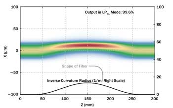
Figure 7. Amplitude distribution in a fiber where the inverse bend radius evolves smoothly. Despite the stronger curvature in the middle, the power loss of the LP01 mode is much smaller.
Apparently, bending effects can substantially deviate from what we might expect. For minimizing bend losses, we should not only limit the maximum curvature, but also avoid abrupt changes of curvature. Of course, the behavior depends on many details, such as the numerical aperture and the number of modes. Numerical simulations are a valuable tool for finding out what exactly happens in the bent fiber.
Meet the author
Dr. Rüdiger Paschotta is the founder and president of RP Photonics Consulting GmbH in Bad Dürrheim, Germany; email: [email protected]. He is also the developer of the RP Fiber Power software, used for all diagrams in this article.