Dr. Robert LaBelle, QImaging and Photometrics
New sCMOS cameras overcome rolling-shutter artifacts by combining the best of both global and rolling shutters to achieve the simultaneous exposure with all rows, all while maintaining the frame rate and low noise benefits of rolling-shutter readouts.
Since the inception of digital microscopy, scientific-grade charge-coupled device (CCD) cameras have been the standard imaging technology for many cell biologists because of their sensitivity, linear response to light and low noise characteristics.
But as research probes deeper into dynamic cellular processes, imaging requirements have grown more demanding. Low-light, high-speed environments are becoming more common, and achieving an acceptable signal-to-noise ratio and high temporal resolution can be difficult for CCD cameras in these situations.
For live-cell fluorescence applications, many researchers are considering scientific complementary metal oxide semiconductor (sCMOS) technology as a CCD alternative because of its ability to image very weak fluorescence with high frame rates, even when using large, high-resolution sensors.
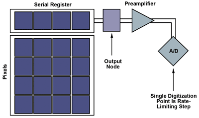
Figure 1. Basic schematics of CCD sensor architecture. A/D = analog to digital. Images courtesy of QImaging and Photometrics.
As with any tool in cell biology, choosing between a CCD or sCMOS-based camera depends heavily on your research objective. Applications requiring longer exposure times, from minutes to hours, are well suited for CCD cameras because of their low dark current, precise photometric response and (with back illumination) incredibly high quantum efficiency. CCD-based cameras perform very well for imaging bioluminescence or chemiluminescence from Western blots.
Live-cell applications are more suited to sCMOS technology. In vivo fluorescence imaging requires maintaining a sufficient signal-to-noise ratio while trying to reduce exposure times to maintain high frame rates, and to reduce fluorescence excitation energy to maintain cell viability.
In these brief examples, choosing between cameras with CCD or sCMOS sensors is determined by frame rate.
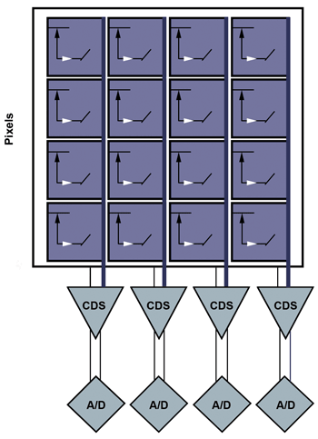
Figure 2. sCMOS sensor layout: sCMOS has one readout per column, allowing a full row to be digitized at once. CDS = correlated double sampling.
CCD frame rates are limited by the charge-transfer process. The signal collected in each pixel is transferred from pixel to pixel, potentially thousands of times, to a single output node where the signal is measured by an off-chip analog-to-digital converter (ADC). This sequential charge-transfer approach to a single output greatly limits frame rates as the number of pixels increases (Figure 1).
Multitap CCDs address this slowdown using a divide-and-conquer approach that increases the number of outputs, effectively subdividing the pixel array to allow sections to operate in parallel. While this increases camera cost and complexity, specialized signal processing chips assist when running two to four taps.
sCMOS sensors take the divide-and-conquer approach even further, using thousands of on-chip signal processors and associated ADCs to digitize each pixel in a given row simultaneously (Figure 2). Further, transistors present in each pixel allow sCMOS sensors to select the row to be measured, without going through a sequential charge transfer of each row. The parallel readout scales well with increasing pixel count, and can be pushed even faster using the same concept as multitap CCDs in which multiple rows are digitized at the same time (Figure 3).
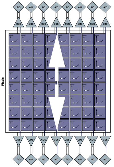
Figure 3. An sCMOS system with split readout allows two rows to be digitized at the same time.
Readout modes, image capture
sCMOS sensors have one additional trick for delivering faster frame rates: overlapping the measurement of one row of pixels while the remaining rows are still being exposed. This unique sCMOS readout mode is known as rolling-shutter mode, as the row currently being digitized “rolls” across the sensor from the top to the bottom. Rolling-shutter mode exposes each row for the same amount of time but at different points in time (Figure 4).
In contrast, global-shutter readout modes expose each and every pixel simultaneously. This does not have the benefit of overlapping exposure and readout to achieve higher frame rates, and in general requires more transistors per pixel, leaving less light-sensitive area.
Common rolling-shutter challenges
A rolling shutter can achieve faster frame rates than a global shutter, but the time delay between row exposures can create disadvantages as well. Many users of sCMOS cameras are familiar with one of a rolling shutter’s negative aspects, the “Jell-O effect,” seen as unnatural wobble in a video stream when relative motion exists between the camera and object.
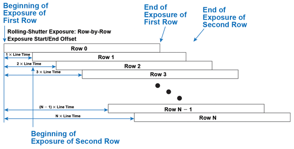
Figure 4. Rolling-shutter readout: Each row has the same exposure length, but starts and stops at different moments in time.
In either readout mode, imaging moving objects means that researchers must take into account the object’s size and velocity to minimize blur. In situations where an object moves a significant distance relative to the time it takes to digitize a row, global-shutter readout may be the only solution.
Even when fast motion is not present, the temporal artifacts of rolling-shutter readout can be observed when rapidly switching between fluorescence excitation wavelengths. To ensure all rows are exposed simultaneously and before readout begins, synchronization between the camera and light source is required. To achieve this precise synchronization, microscopists run a triggering cable from the camera to the light source so that the light is activated at the start of each exposure.
Though this organization is straightforward with a global shutter, where each row is exposed at exactly the same time, synchronizing a rolling shutter is more complex. In rolling-shutter mode, each row is exposed to the light at a slightly different point in time. The definition of “start” and “finish” becomes unclear, as it could refer to any individual row’s exposure behavior. When the exposure time approaches the time necessary to digitize all rows, the difference in the start of exposure for every row is evident as shading (Figure 5).
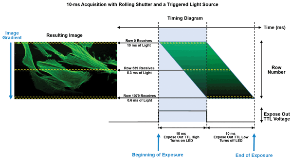
Figure 5. Illustration of the vertical intensity gradient caused by the time delay between each row of pixels in rolling-shutter readout mode with an sCMOS camera and a triggered light source. TTL = transistor-transistor logic.
For multichannel fluorescence imaging, where the light source alternates between excitation wavelengths for each exposure, rapid switching between excitation channels can result in channel blending. This occurs because the light source is synchronized with the start and stop time of the first row’s exposure. The next excitation wavelength begins to illuminate the specimen before the last row is exposed and digitized.
sCMOS in global-shutter mode
Dealing with this complexity is why many early sCMOS proponents choose global-shutter readout as their primary readout method. Similar to interline CCD cameras, when an sCMOS sensor operates in global-shutter mode, every pixel is exposed at the same time.
Using global-shutter readout with an sCMOS sensor will address many of the drawbacks associated with rolling-shutter mode. Most noticeably, global shutter removes spatial aberrations from fast-moving objects, eliminates gradients with triggered illumination and allows fast excitation-channel switching without overlapping channels.
This comes, however, at the expense of frame rate – the primary advantage of choosing sCMOS over CCD.
Rolling-shutter speeds, global-shutter exposure
The optimal solution for sCMOS sensors would combine the fast frame rates of a rolling shutter with the exposure simplicity of a global shutter.
A possible solution can be found in the custom triggering mode featured in QImaging’s optiMOS sCMOS camera. This custom triggering mode can achieve a global-shutter exposure with a rolling-shutter readout. The triggering mode rapidly shutters a high-speed light source, pulsing the light only when all rows in the frame are simultaneously exposed to achieve a global exposure. During this process, the camera is kept in rolling-shutter mode to maintain high frame rates and low read noise. This functionality is referred to as All Rows Mode (Figure 6).
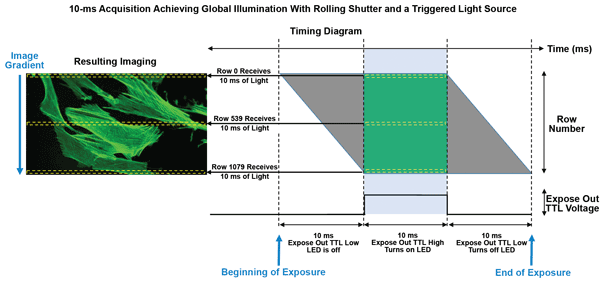
Figure 6. Diagram demonstrating artifact-free global illumination using 10-ms exposures and the optiMOS’ All Rows Mode to trigger a single-excitation-channel light source.
For All Rows Mode to work effectively, especially at fast frame rates, there must be precise synchronization between the camera and high-speed light source. New high-speed sources can shutter the light in a very precise manner, making it possible to achieve uniform global illumination, as well as rapidly switch between multiple excitation wavelengths.
This is demonstrated in Figure 6, where, by entering a 10-ms exposure and selecting snap, the camera receives a software or hardware trigger to begin acquisition. Row 0 on the sensor begins exposing, but initially the Expose Out hardware trigger signal from the camera stays low.
Each row subsequently begins its exposure; the Expose Out signal remains low until the very last row of the frame begins exposing. Once the last row starts its exposure, the Expose Out line goes high. This rising edge of the Expose Out signal is used to trigger a high-speed light source such as a laser or LED, which turns on and stays on the entire time the Expose Out line is high.
This event marks the beginning of the full frame’s exposure, as all rows have started their exposure and the Expose Out line has turned on the excitation source.
All rows continue to expose for the length of time defined by the user (10 ms). Once this time has elapsed, the Expose Out line drops, turning off the excitation source. Row 0 then begins readout, followed by the cascading readout of every remaining row.
In this mode, the camera continues to expose and read out in a rolling-shutter fashion, but the Expose Out line is used to gate the illumination so that all rows in a single frame collect light for the same length of time and at the same instant in time. The result is a global illumination, achieving the same effect of a traditional global shutter and avoiding any potential spatial distortions caused by the rolling shutter.
For this mode to function properly, especially at high frame rates, precise synchronization between the camera and a high-speed light source is required. The time required to turn the light on and off absolutely must be very small relative to the exposure time of the camera. New high-speed light sources capable of shuttering the light on the order of 10 µs make it possible both to achieve a uniform global illumination in All Rows Mode and to switch rapidly between multiple excitation wavelengths.
This mode is most useful for fluorescence microscopy applications that require multiple excitation wavelengths. With the camera synchronized exactly to the light source, all rows capture an image and are exposed to a single excitation channel at the same time, completely avoiding any rolling-shutter artifacts.
Choosing the best tool
CCD and sCMOS both offer their own distinct advantages for different bioimaging applications. sCMOS cameras present a considerable speed improvement over CCD, especially in rolling-shutter mode, but the overlapping readout behavior and time delay between each row’s exposure can introduce artifacts in some scenarios.
Although not every researcher requires the frame rate sCMOS can provide, with slight changes in experimental setup, most will benefit from the sensitivity, interactivity and convenience that comes with smooth live image capture across a large field of view. The ease and richness of image data that can be captured with sCMOS will continue to inspire new research methods capable of peering deeper into cellular processes.
Meet the author
Dr. Robert LaBelle is vice president of marketing at scientific digital camera companies QImaging and Photometrics, in Tucson, Ariz.; [email protected].