A new class of interferometer that incorporates a tunable laser source makes precise measurements of both diffuse and specular objects. Using real-time feedback, component manufacturers can control processes to reduce scrap and rework, improve device performance and cut costs.
Dr. Thomas J. Dunn, Corning Tropel Corp.
A growing number of precision component manufacturers are machining objects that have micron- or submicron-level tolerances on parameters such as flatness, thickness and parallelism. They are discovering that the assembly of subcomponents that are each within tolerance nevertheless can result in a whole that does not function properly because of tolerance stack-up. This problem requires more-frequent metrology during the assembly process so that the subcomponents can be properly matched. Consequently, there is an increased emphasis both on accurate subcomponent metrology and on assembly metrology.
Conventional, single-wavelength interferometers offer excellent height resolution over a continuous, smooth surface; however, they cannot measure rough surfaces or the relative distance between discontinuous regions. Recessed surfaces are a good example of a discontinuous region that may be on a plane more than 20 mm from the datum surface. White-light interferometers offer the additional capability of measuring discontinuous surfaces, but they can be slow and inflexible.
Frequency-scanning interferometry, developed for Corning Tropel Corp.’s LightGage product, overcomes these limitations. The advantages of the technique are best understood when it is compared with traditional interferometric methods.
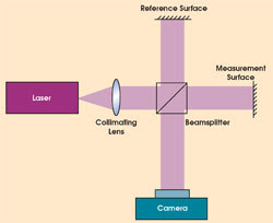
Figure 1. A conventional, single-wavelength interferometer compares the surface height variations from the test surface with those from an ideal reference.
In a single-wavelength Michelson interferometer, a beamsplitter separates the output of a laser into a reference and a measurement arm (Figure 1). The two laser beams are reflected from their respective test or reference surfaces and are directed back into the beamsplitter, where they recombine. A high-resolution camera records the resulting interference pattern. If the reference is a perfect mirror, the pattern shows the deviation of the test surface from an ideal plane (Figure 2).
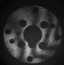
Figure 2. An interferogram of a spacer used in a fuel injector application displays dark and light bands — interferometric fringes that show the deviation from an ideal plane.
Creating a surface height map of the test surface involves the use of conventional phase-measurement interferometry algorithms, which require the introduction of known phase changes between the test and reference arms. One way to do so in the Michelson interferometer is to employ a piezoelectric transducer to move the reference mirror in subwavelength steps and to collect a number of interferometric images (frames of data) of the surface. For each image that is collected, a constant phase change is added between the reference and test arms.
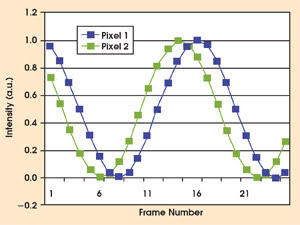
Figure 3. To generate a surface height map using single-wavelength interferometry, the intensity change of each pixel is obtained by moving the reference mirror in small steps. The relative height variation is obtained by measuring phase changes between pixels.
Figure 3 plots the intensity variation, or modulation, of two pixels from Figure 2 seen by the camera for all the frames that are collected. The height difference h for the pixels is given by the expression:

where λ is the wavelength of the interferometer and Δf is the phase difference between the pixels. This calculation is performed for all of the pixels in the interferogram to generate a surface height map. Variations in height that are larger than one wavelength can be measured only if the surface is smooth enough to enable phase-unwrapping algorithms to work.
This technique can be very fast because only small movements of the reference mirror are required to collect the data. It also offers very high resolution and accuracy because one cycle of intensity variation — called a fringe — corresponds to one-half the wavelength of the laser source. Resolution typically is better than 0.01 μm.
There are two major drawbacks for such single-wavelength interferometers: They cannot measure diffuse or rough surfaces, and they cannot measure step heights between discontinuous regions.
For diffuse surfaces, the height variation within a pixel and between pixels often is substantially greater than the measurement wavelength, resulting in interferograms that look like speckle patterns. In these cases, conventional single-wavelength interferometry employing standard phase-unwrapping algorithms does not work because there is no good fringe pattern.
White-light interferometers overcome both of these limitations. Their optical arrangement is similar to the single-wavelength setup, but a white-light source that emits radiation over a broad range of frequencies replaces the laser. The surface under measurement is simultaneously illuminated with a range of source frequencies. White-light fringes are localized and are visible only when the optical paths for the reference and test arms are very well matched. A measurement requires that the reference mirror or test object be scanned precisely in the direction of the illumination to locate the interference fringes.
Although white-light interferometry is very capable, the requirement of a moving reference can make it impractical for the measurement of deep or large objects. Furthermore, the measurement time increases directly with the measured range.
Frequency scanning
Unlike white-light interferometry, the measurement time is independent of range in frequency-scanning interferometry. The technique uses the same optical arrangement as the Michelson interferometer, but it incorporates a laser source that is tunable over a range of laser frequencies (bandwidth >10 nm).
In a manner similar to single-wavelength interferometry, it collects multiple interferometric images of the part under measurement. For each image or each frame of data, the laser frequency is changed by an equal increment. The intensity of each pixel will vary by a frequency that is determined by the mismatch in the distance between the reference and test arms.
As mentioned, the modulation frequency for all the pixels is constant for single-wavelength interferometers, and the phase is measured to determine the changes in relative distance across the test surface. For frequency-scanning interferometry, however, the modulation frequency for all the pixels is not constant, and the modulation frequency is measured directly to obtain the absolute distance between the reference and test surfaces (Figure 4).
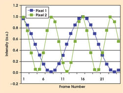
Figure 4. In frequency-scanning interferometry, the modulation of each pixel is obtained by scanning the laser frequency in small steps. The absolute height for each pixel is obtained by measuring the modulation frequency for each.
One advantage of frequency-scanning interferometry is that the height of each pixel is obtained independent of its neighboring pixels using fast Fourier transform algorithms to determine the modulation frequency. No phase-unwrapping algorithms are utilized. As a result, it is possible to measure rough and diffuse surfaces in which there can be very large differences in height from pixel to pixel (Figure 5). Similarly, this enables the measurement of discontinuous regions separated by distances greater than 20 mm.
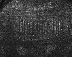
Figure 5. There are no clear interferometric fringes from a rough surface, such as this penny. Rather, the interferogram looks like a speckle pattern. This image would be impossible to analyze using conventional phase-unwrapping algorithms.
The technique also enables a variety of unique instrument design forms. By eliminating any precision motion requirements, the interferometer becomes very compact and modular with few, if any, moving parts. Measurements are performed in seconds, independent of the measuring range.
Another feature is that the interferometer can be located remotely from the laser source (Figure 6). A single-mode optical fiber transmits the variable-frequency illumination to the instrument, which incorporates the reference arm and high-resolution camera. This design enables new applications for interferometry, such as the in-line measurement of precision components or assemblies.
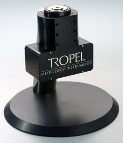
Figure 6. The frequency-scanning interferometer’s head is mounted on a small stand. The tunable laser source is plugged in through a fiber optic cable, so it can be remotely located. A small part is shown placed on the measurement window at the top of the interferometer.
Frequency-stepping interferometry offers many advantages over conventional approaches: fast measurement times, a scalable field of view for the measurement of various part sizes, a dynamic range of tens of millimeters, submicron precision, compatibility with surface finishes from cast to polished, and compatibility with a wide range of materials, including metals, ceramics, glass and plastics.
Applications
Figure 7 displays the parameters that can be measured easily for individual component or assembly applications. The flatness of any surface — as well as the parallelism and height separation between surfaces — can be measured with submicron accuracy and repeatability. With two sensors, data may be collected simultaneously on both end faces of an object so that part thickness also can be measured.
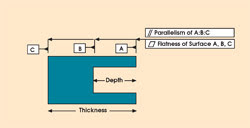
Figure 7. The flatness of any surface on a component, as well as the parallelism and separation of any two surfaces, can be measured using frequency-scanning interferometry. Different surfaces are labeled A, B and C.
An example of an application of the technique is the measurement of an automotive fuel pump component (Figure 8). A typical design uses an impeller to pump fuel through a cavity formed by two housing halves, one of which features a groove in the bottom to provide the fluid flow to the impeller’s teeth or vanes. Proper operation requires that the flatness, parallelism and height between the outer ring and the recessed surface be tightly controlled.
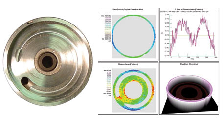
Figure 8. Proper operation of today’s automotive fuel pumps requires tight control of the flatness, parallelism and height between the outer ring and the recessed surface of the impeller housing.
As another example, consider that the need for better data storage solutions has driven manufacturers of hard disk drives to increase disk speeds (reducing seek times) and to lower the flying heights of the read/write-head-to-disk interfaces (increasing data density). Designers once were concerned only with the flatness of the disk itself, but with ever-higher rotation speeds and ever-smaller fly heights, the characterization of the flatness, parallelism and height between surfaces in the drives is critical. The wavy washer shown in Figure 9 is a critical component that must be tightly controlled.
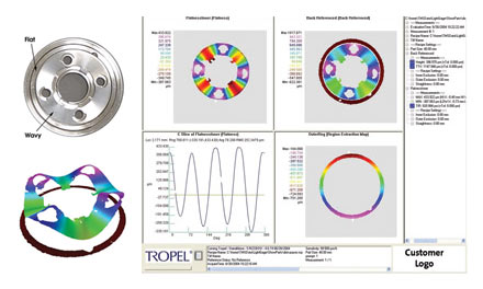
Figure 9. Today’s hard disk drives require manufacturers to characterize the flatness, parallelism and height between different surfaces, not simply the flatness of the disk itself. This wavy washer must be tightly controlled in manufacture to ensure proper operation of the drive.
Frequency-scanning interferometry enables a new class of metrology instrument that will greatly expand the role of optical metrology in precision manufacturing. The technique encompasses the capabilities of single-wavelength interferometry and — thanks to digital signal processing — those of white-light interferometry without requiring moving optics. There are many potential applications of the technology, including the measurement of precision machined parts and complex assemblies of components.
Meet the author
Thomas J. Dunn is the engineering manager at Corning Tropel Corp.’s Metrology Instruments Div. in Fairport, N.Y.; e-mail: [email protected]. He received a PhD in optics from the University of Rochester in 1994 and holds 10 patents for optical systems and techniques used in semiconductor lithography, interferometry and metrology.