Time-integrated laser-induced fluorescence spectroscopy is one of the most sensitive techniques based on the interaction between light and matter. It works on the basis of registering direct radiation emitted by the substances to be detected, and offers exceptional detection sensitivity and spatial resolution.
DR. JENS BUBLITZ, KIENZLE PROZESSANALYTIK GMBH
The analysis of technical surfaces is crucial for the optimization of lubrication, coating or cleaning processes, especially with regard to achieving and assuring better quality of final products. Frequently, the essential requirements for an additional, specific production step cannot be controlled sufficiently, since most laboratory methods provide only limited and randomly appropriate information.

Figure 1. Principle of time-integrated fluorescence detection.
An efficient inline and online process analysis can, therefore, contribute significantly to the prevention of quality defects. The reduction in production losses saves resources and essentially increases the added value of a process. In principle, the required surface analysis can be divided into two different application areas: first, the monitoring and evaluation of functional coatings, and second, the analysis of surface cleanliness.
Common methods — chemical analysis, thermal treatment of product samples with a subsequent gravimetric evaluation, or CO2 (total organic carbon, or TOC) gas analysis — are based on taking product samples. Plasma or mass spectroscopy are vacuum-based methods, where an invasive interaction with the respective surface takes place. Comparatively, optical methods have the big advantage of an analysis without any contact to the surface to be investigated. However, most currently used methods, such as IR-, Raman- or diffuse-reflectance spectroscopy, as well as the ellipsometry, are dependent on constant reflection properties of the examined product surface. Furthermore, to determine a surface amount or layer thickness derived from transmission or absorption behavior, an initial intensity is always needed as a reference value.
The special time-integrated laser-induced fluorescence spectroscopy, or LIF(t), technique is a process-analytic, contact-free procedure that allows a nondestructive analysis of the surface cleanliness directly in production processes. The method can also be applied for qualitative and quantitative monitoring of lubrications or other applied functional coatings.
Physical and technical principle
The basic principle of laser-induced fluorescence spectroscopy is the absorption of the exciting laser radiation through the substance to be detected. In this process, an interaction of laser radiation with fluorophore regions in the electron structures of the target molecule takes place. The absorbed energy is re-emitted by the molecules as a new light, the so-called fluorescence, in times on a nanosecond scale (10−9 s). This process is one of the most efficient interactions between light and matter, and it occurs in dependency of the substances involved and substrate media, with measurably different speeds. A statistical registration of the single photons here offers, in comparison to other spectroscopic methods, a detection of very low quantities of material with particularly high sensitivity.
Laser emission in the UV spectral range (e.g., 266 or 355 nm) might lead to a fluorescence excitation of the molecules that should be detected (wanted signal), as well as a possible background signal caused by organic matter on the surface below the analytical target.
Registering only the spectral intensity distribution of the fluorescence doesn’t necessarily lead to a significant separation of the substance spectra. Therefore, a time-integrating approach is included in the procedure to observe the decay times of fluorescence signals in a suitable wavelength range. After each single laser pulse excitation, lasting about 0.5 ns, the time decay of the fluorescence radiation is registered in two appropriately positioned windows. Here, the time-integrated intensity is measured as values I1 and I2 in order to separate the wanted signal from the background, as indicated in Figure 1. In a third time window, positioned about 1 µs after the second one, the ambient light intensity I3 is registered and used to correct the values of I1 and I2.
Optical excitation is performed by a specially designed, passively Q-switched UV microchip laser from Teem Photonics SA with a repetition frequency in the range of 11 kHz. Single laser pulses with an emission wavelength of 266 or 355 nm and an average optical output power below 2 mW are generated. These are transferred via a quartz fiber bundle of up to 20 m in length and a probe head directly into the process. Here, a typical output power of 250 µW is used.
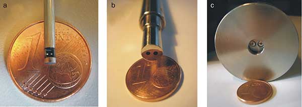
With a second quartz fiber bundle, the transmission of fluorescence signals to the detector is arranged. Therefore, the corresponding detection head contains no active components, and is suitable to be used in harsh and demanding environmental conditions. If there is a risk of contamination of the fiber optics, automated pollution prevention is ensured by using a compressed air or gas flushing, or appropriate ultrasound techniques. Figure 2 shows examples of three different configurations for various applications of inline surface analysis.

Figure 2. Different configurations of detection heads for surface analysis: (a) 90° arrangement for the investigation of walls in boreholes with 2-mm diameter; (b) standard detection head for surface analysis (diameter = 8 mm); (c) standard detection head with compressed-air flushing to ensure an automatic pollution prevention of the fiber optics (diameter = 35 mm).
By choosing the configuration and positioning of the probe (distance and angle) with respect to the surface of investigation, the spot size of the effective detection area can be adapted to the process requirements.
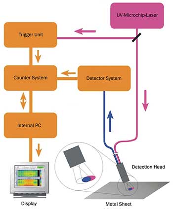
For a very sensitive detection of single-fluorescence light events (photons), a photomultiplier tube is used. An application-specific wavelength configuration is provided by a special combination of optical filters in front of the detector. Using a statistical single-photon counting method, the detector pulses are evaluated according to the time-integrated method. Via a calibration function, the respective measured quantity is calculated and displayed depending on the application with a high sampling rate of every 10 ms or even every second. Since each single-fluorescence measurement takes place in the nanosecond timescale, the results of surface measurements on moving parts or sheets do not depend on the process speed, which could be more than 2000 m/min. Figure 3 demonstrates schematically the technical implementation of the time-integrated laser-induced fluorescence analysis.

Figure 3. Schematic setup of the time-integrated fluorescence detection system.
Industrial applications
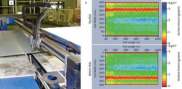
A versatile field of application of coating analysis is the specific detection of lubricants on coil material (single boards), and on prefabricated parts in the steel and aluminum industries. Coil material is customer-specific and lubricated with different kinds of prelubes for the automotive industry. Here, the laser-induced fluorescence detection technique is able to monitor inline and online deviations from the specified layer thickness in a typical range of up to 3 g/m2, and in particular to find possible dry areas with size greater than 15 mm at line speeds of up to 600 m/min. Figure 4a shows a typical installation of a system for simultaneous inspection of the upper and lower surfaces of coil material with a width of up to 2 m. It was integrated in an existing production line.
For the measurements, two single detection heads with compressed-air flushing (Figure 2c) are synchronously moved with a travel speed of 0.5 m/s across the surface of the metal strip, and the current local layer thickness is determined quantitatively with a sampling rate of 10 ms. Figure 4b demonstrates typical results for the top and bottom surface, each in separate color gradient plots. The green indicates an optimum accordance with the predefined amount of prelube for the lubrication; the blue color indicates an over-oiling. The red is a warning for dry areas, which in most cases are not observable by a direct visual inspection.

Figure 4. Fluorescence detection system for a simultaneous inline and online inspection of the top and bottom sides of lubricated coil material: (a) installation situation and (b) typical presentation of the results in a color gradient graph.
Beyond lubrication control, there is a variety of other applications in the field of metal processing, where the inline monitoring of special functional layers might increase the process efficiency, or lead to better, more stable and reliable product quality. Some examples include passivation coatings, lacquers, films, polymers, primers and adhesives.
In the metal working industry, large amounts of production additives, such as cooling lubricants, are used to ensure high process reliability in forming or machining production. Residuals of these coatings remain as contaminants on the workpiece surface and will be unavoidably carried over into subsequent process steps. Special manufacturing processes are very sensitive to the surface cleanliness of the working material, such as annealing, bonding, coating, painting, etc. Therefore, in most applications, the workpiece is cleaned prior to further processing. The continuous monitoring and evaluation of technical surfaces concerning residues of process additives and cleaning media is another important application of the fluorescence spectroscopic surface analysis.

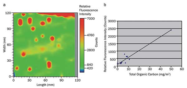
Figure 5. Typical results for detection of rolling-oil residues on aluminum sheets: (a) color gradient plot of measurement with a two-axis translator and (b) correlation of the fluorescence data to the results of a surface carbon analyzer.
In the case of production that uses the rolling process, aluminum, steel or copper sheets are annealed in order to remove remaining rolling oil on the surface. Commonly, customers of an aluminum or copper plant require a leftover of rolling oils and other production media of not more than 5 mg/m2 on the surfaces of their final products.
Figure 5 shows the results of such a determination of rolling-oil residues on aluminum sheets. By using a two-axis translator unit, a complete area screening of sample sheets in the size of 100 mm × 100 mm with a spatial resolution of 2 mm is possible in order to determine the distribution of locally varying degrees of contamination (Figure 5a); a comparison of the fluorescence data averaged over the entire sample surface is plotted in Figure 5b. The results were determined subsequent to the fluorescence measurements with a standard surface carbon analyzer, based on the determination of the TOC.
Meet the author
Dr. Jens Bublitz is manager of R&D at KIENZLE Prozessanalytik GmbH in Flensburg, Germany; email: [email protected].