Dr. Christian Wenzel , Innolite GmbH
Ultraprecision machines can provide positioning and lathe centering of mounted lenses in high-performance optics production. Integrated software works with high-precision metrology to offer more economical production for small- and medium-sized companies in the field.
Many modern applications such as camera lenses, telescopes and microscopes use complex systems consisting of multiple lenses. The optical performance of such systems depends on the correct positioning of lenses.
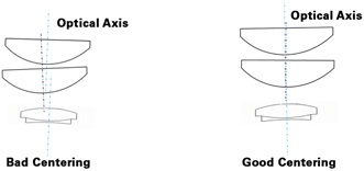
Deviations in location or angle within complex lens systems directly affect the achievable image quality. Besides manufacturing tolerances, such deviations result from alignment and cementing or gluing of lenses into specific mounts. To achieve the optimal performance of lens systems, any errors need to be corrected by machining the mount with respect to the optical axis. The major benefit of such a machining step is the independence of the glue or cement shrinkage that typically occurs during lens assembly. Figure 1 illustrates a lens system without (left) and with centering (right) of the individual optics.

Figure 1. These diagrams show the influence of optical centering: At left, an optical system without centering; at right, an optical system with centering.
State-of-the-art machining technology
State-of-the-art processes to correct centering errors typically adjust the position of a mount with the help of manual or automated alignment chucks in such a way that the mount is aligned to the spindle axis of the turning machine. The discrepancy of submicron mechanical alignment and subsequent clamping for sufficient stiffness in the center turning process requires highly complex mechanical solutions, characterized by high price and the need for sophisticated operator skills. For such state-of-the-art machines, automation or operator-independent process performance is not common. The machines are designed for manually operated individual units. Cost-efficient, reliable production is difficult to achieve. In addition, such highly specialized machines can be used only for the sake of centering optics. Many times the economic justification of investment is difficult to argue, as volume for centering optics and the added value remain limited.
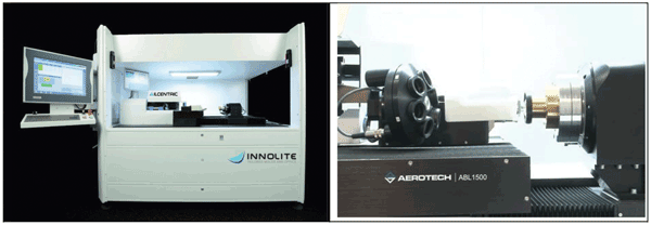
The ILCentric is a machine that does not require mount alignment to a spindle machine (Figure 2). Instead, an autocollimator measures the absolute position of the optical axis with reference to the spindle axis. In this case, the optical axis is skewed and offset in reference to the spindle axis. Using the information about the mount and all reference surfaces, a machine program for an untrue turning process is calculated from this data in a fully automated, repeatable manner.

Figure 2. At left, the machining system measures the absolute position of the optical axis. At right, a working space with sensors.
Since the optical axis is not collinear with the spindle axis, a diamond tool will compensate for linear and tilt deviations with small correction movements comparable to a slow, tool-assisted turning process. These micro movements allow the mount to be centered even if it is not aligned to the spindle axis. This results in a much simpler machine setup where the control system works as an electronic alignment chuck with no need for further mechanical alignment. Hence, mechanical tolerances or manual alignment errors do not affect the achievable centering accuracy. In addition, the clamping of a mounted lens to the machine’s spindle can be designed to be significantly stiffer, resulting in better centering performance with significantly better repeatability.
Proprietary NanoGrip zero-point clamping systems offer 0.5 µm of mechanical repeatability. Such a clamping system allows individual fixtures for different mount geometries to be aligned within seconds. The design of a fixture can be optimized on the base of the zero-point clamping pallet to minimize the deformation influence of the mount itself – one of the dominant sources for the remaining centering error.
A base machine is equipped with either an aerostatic or hydrostatic axis, optical scales, and ironless direct drives in horizontal alignment, enabling nanometer step sizes. The conventional vertical setup for center turning machines is not needed, as no alignment chuck is influenced by
gravitational forces. An air-bearing spindle with nanometer runout is utilized for the workpiece rotation. The spindle can be designed with a hollow rotor to allow for measurement tasks onto the back side of the lens.

An autocollimator measures the optical axis of single lenses, achromats or lens subassemblies. In addition, either a tactile or confocal sensor is incorporated to measure the lenses’ peak positions, the mounts’ diameters or other geometrical features of relevance to the final assembly. The sensors are integrated into the machine and control-system architecture. Due to a PC-based, high-performance control system that follows German industrial standards and software, individual program routines can be preset to allow for user-specific mounting designs, inspection routines and different optical designs.
Affordable high-tech performance
A software-based untrue turning solution, the ILCentric reduces auxiliary process time to less than one minute with ease of use and high precision. As the performance is operator independent and fully software controlled, there exists a centering accuracy of less than 2 µm and less than 0.2 arcmin, a positioning accuracy of less than 0.2 µm, and a diameter tolerance less than 1 µm. As the resulting reject rate falls near zero, the production cost of complex optical systems declines significantly. This reduction in price, combined with the low acquisition cost compared with that of conventional centering lathes, enables even small companies to enter the market of ultraprecise, complex optical systems. In turn, the customer base is broadened and the business risk is reduced. The better opportunities for market entry enable intensified competition in the area of complex lens systems consisting of multiple lenses; this results in additional price reduction for high-end consumer objectives, as well as for objectives used in lithography and microscope applications.
Such a system does not require a specialized and horizontally installed alignment chuck; it can function as a conventional diamond turning lathe operated in conventional G-Code programming mode. The justification for investment does not depend on center turning jobs alone but can also include standard diamond turning jobs to generate mirrors, lenses or high-precision mechanical parts.
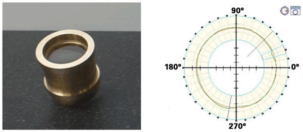
Ultraprecise, untrue turning operation does not influence the accuracy that can be achieved at the desired part. A sample lens assembly consisting of a convex sphere and a brass mount that has been centered with the machine is demonstrated in Figure 3. The relevant surfaces to be machined are a front side, an outside diameter and a back side. Two diamonds aligned at adjustable angular positions allow for the joint machining of front side, diameter and back side in one setup.

Figure 3. Machining of a sample part: At left, a lens assembly to be machined; at right, cylinder deviation after machining.
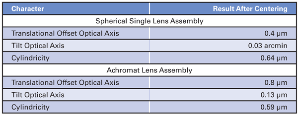
Centering results for assembly The achromat setup is less precise in centering compared with the single spherical lens assembly. This is because cementing the achromat introduces an inaccuracy that cannot be compensated for during center turning. Table 1 shows the values of both types of lens assemblies after machining.

The first and last surfaces of the achromat assembly can be used to determine the optical axis, as one option. Alternatively, the optical axis of the first lens and the optical axis of the second lens of the achromat can be used for averaging. The two strategies result in different remaining overall errors; the choice depends on the individual application.
Of fundamental importance to achieving high quality is machining the mount surface with a single crystalline diamond. This approach keeps cutting forces at a minimum and avoids mechanical deformation of the workpiece and machining structure. Hence, mounting materials are limited to nonferrous, diamond-machinable materials. In cases where steel or ferrous materials are required, the machine can be equipped with an ultrasonic unit that enables diamond machining of steel. As a limitation, only the front-side geometric features and outer diameters can be machined. If back-side machining is necessary, the mount geometry must be reclamped based on a zero-point clamping system, such as NanoGrip.
Meet the author
Dr. Christian Wenzel is CEO and managing director at Innolite GmbH in Aachen, Germany; email: [email protected].