Proper optical methods increase accuracy.
Roger Rypma, Coherent Inc.
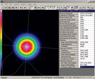
Measurement of spatial beam intensity distribution — a beam profile — and of beam propagation characteristics is an integral part of today’s many high-precision, laser-based applications where beam quality is critical. The basic definitions and techniques for these laser measurements are documented in several ISO standards (ISO 11146 and 13694, in particular). These methods include various aperture-scanning techniques — such as slits, knife edges and pinholes — and techniques based on array detectors, such as CCDs, which are integrated into a variety of commercially available instruments (Figure 1). Their measurement accuracy is dependent on the use of proper optical techniques for attenuation of the laser beam.

Figure 1. Coherent’s BeamView Analyzer CCD-camera-based beam diagnostics system shows many of the ISO standard laser measurements.
It’s important to consider both optical quality specifications and recommended methods for beam attenuation that minimize the impact of distortion and scatter on measurement accuracy. Here we focus on the most common case of collimated (or approximately collimated) beams.
Sources of error
A danger with any optical beam sampling or attenuation method is that it may introduce significant beam distortion and background scatter. How much distortion is significant? In terms of most commercially available beam-profiling instrumentation, distortions of less than λ/4 rms are undetectable; this sets the upper limit on allowable measurable error.
In general, wavefront distortion through a number of components can be calculated by taking the square root of the sum of the squares of the wavefront distortion from the individual components. For example, six components, each of which introduces λ/10 distortion, could be used together and produce only λ/4 of overall wavefront distortion.
Surface defects and bulk material flaws that produce scattered light are also potential sources of error. Typically, a scratch-and-dig specification of 10-5 is recommended for the surface of all laser-related attenuation optics. Minimizing both bubble content and stress birefringence also is advised for components that are to be used transmissively. Furthermore, low values for all these parameters also increase the ability of the component to handle higher laser power and minimize the chance of damage, bulk distortion or thermal lensing.
Interference fringes caused by reflections from parallel surfaces, either internal to an optic or from adjacent components, are another common source of distortion. Localized coating defects, such as pinholes, burn spots or scratches, also are a typical source of scatter.
Optical components that are at least 20 percent larger than the beam diameter should be used to reduce the chance of edge diffraction effects. This is also advisable because the surface accuracy and quality specifications on most optics apply only to the central 90 percent of the component.
Finally, it should be noted that, even when using the finest laser-grade components, one must be aware of the presence of contaminants such as ordinary dust, fingerprints or the residual from cleaning; e.g., scratches, solvent residue and lint. Contaminants are by far the most common source of scatter distortion and surface damage to components or coatings when working with very high power lasers.
High-power fixed attenuation
Beam polarization is another factor to consider. Any optical system — particularly its attenuation — that alters beam polarization or is polarization-dependent can produce erroneous results for beams that contain a mixture of polarization states. This is because the polarization ratio can vary spatially across the beam profile, such as birefringence in a solid-state Q-switched laser.
When measuring high-power laser beams, some amount of optical attenuation is generally required to bring the incident power below the damage threshold of the detector. Imaging systems and knife-edge scanners are usually limited to lower-power beams than pinhole or slit scanners because they sample the entire beam at once. Furthermore, it is typically desirable, especially for CCDs, to adjust the peak power incident on the detector to a value at or just below its saturation level, so as to utilize the entire optical dynamic range of the device.
The general approach for the attenuation of high-power laser beams is to first use nonabsorptive, fixed-attenuation value components capable of handling very high powers, followed by lower-power components, such as filters or polarizers, that allow variable intensity adjustment after the beam has been reduced to manageable levels.
For the first high-power attenuation stage, the simplest approach is to use the first-surface reflection off an uncoated laser-grade substrate. In this approach, the beam to be measured is not transmitted through the material, and relatively inexpensive substrates can be used with no concerns about distortion by the bulk material. Typical laser-grade specifications for these components are λ/10 to λ/20 surface flatness and 10-5 surface quality, which can be found on commercially available uncoated laser mirrors.

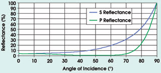
Figure 2. This graph shows reflectances for BK 7 glass at 1.06 μm as a function of the angle of incidence. Reflections off surfaces at any angle greater than 15°incidence can produce different amounts of attenuation in the s- and p-polarization planes.
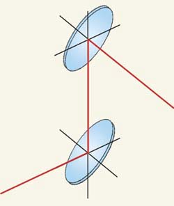
The reflectance from an uncoated substrate is highly dependent upon the wavelength, angle of incidence, polarization and index of refraction of the material (Figure 2). For angles of incidence of <15°, the difference in reflectance between the polarizations is typically small enough to be ignored. However, when dealing with beams of mixed polarization state and higher angles of incidence (especially around 45°), the simplest way to compensate for this is to use components in pairs, with one rotated 90° in azimuth relative to the first reflector, and at the same angle of incidence. This will always cancel out any polarization-related reflection effects (Figure 3).

Figure 3. Using a pair of reflectors such as these, at 45° but rotated along the beam path by 90°, compensates for beams of mixed polarization state and higher angles of incidence.
This method allows the use of laser beams in the gigawatt-per-square-centimeter peak-power range without damage. By using a series of uncoated, front-surface reflectors, major reductions in beam intensity can be achieved without significant beam distortion. Using the example given earlier, six λ/10 uncoated reflectors can be used in series with an overall wavefront distortion of λ/4.
By using the reflectors in opposing pairs at 45°, so that three “see” s-polarization (rs ~ 10 percent) and three “see” p-polarization (rp ~ 1 percent), the total attenuation for such a system at 1.064 μm would be approximately 0.1 × 0.013, or 10–9. This provides not only a tremendous polarization-independent reduction in beam intensity, but also a very broad bandwidth. It would be particularly useful and economical for use with high-power tunable lasers.
Other attenuation techniques, such as diffractive optics and the use of back-mirror leakage, can be effective. They are less desirable, however, because they can introduce bulk distortion and surface scatter into the beam.
Low-power variable attenuation
After the major reduction in beam intensity is achieved, it is useful to have an intensity adjustment range of at least 1000:1 in the final stage. This adjustment will bring the beam power to the exact level necessary for optimum measurement by the detection system. Even when working with a single-wavelength laser operated at one power level, the adjustment may be necessary to compensate for changes in beam diameter or spot size (and thus power density) that may be encountered when making measurements at different points along the beam path.
The most commonly used general-purpose filters for low-power beam attenuation are metallic-coated-glass (or fused silica) neutral-density filters and neutral-colored glass, supplied by vendors such as Schott and Hoya Corp. Although metallic filters are available for ultraviolet, visible and near-infrared use, the neutral-colored-glass absorption filters are usable only above about 400 nm.
Because most off-the-shelf metallic and glass neutral-density filters are marketed for general-purpose laboratory use, surface flatness is relatively poor. Furthermore, the bulk material used for these components is not considered “laser grade,” meaning that there may be significant scattering contributions from bubbles, polarization effects due to birefringence, and nonlinear absorption due to striae. Thus, wavefront distortion from even a single filter can typically exceed the λ/4 specification.
Additionally, because surface quality on commercial filters is usually 60-40 scratch and dig or worse, the filters may introduce a significant amount of scattered light into the system. For metallic-coated neutral-density filters, coating pinholes represent another source of stray light. The best results are obtained with a coating pinhole specification of less than 5 μm.
Another typical problem with these filters is interference fringes from internal reflections, which change the intensity profile of the measured beam and produce erroneous measurement results. For metallic filters, this effect is worst at low attenuation values; for those with greater than 30 percent attenuation (optical density = 0.5), the interference pattern generally has a lower contrast than the dynamic range of the sensor system. One way to greatly reduce this problem is to use an antireflection coating on the second surface of the filter.
When multiple filters are employed, a small tilt of about 0.5° should be used to avoid creating interference fringes from parallel surfaces of adjacent components. The number of filters, as well as the overall thickness, also should be kept as low as possible. This will minimize both the number of optical surfaces and the total bulk material that could contribute to distortion.
Laser-grade attenuation optics typically are not found in the product offerings of most vendors of catalog optics. However, companies that specialize in beam-diagnostics instrumentation offer them in various forms. For example, Coherent Inc. provides an adjustable neutral-density glass filter assembly and high-power beam attenuator system that meets the flatness and surface-quality specifications outlined earlier.
Finally, neither glass nor metallic neutral-density filters can handle high-power laser beams. High-power beams can quickly damage metallic filter coatings, and neutral-density glass materials may heat up enough through absorption to induce thermal lensing. In these cases, high-power attenuators should be used before these filters to reduce the beam intensity.
Polarizers also can be used with many lasers to provide adjustable power attenuation. Once again, the standard dichroic polarizers available from most optics suppliers do not have the requisite optical quality for precise beam measurements. Furthermore, the dynamic range of the adjustment offered by dichroic polarizers is only about 50:1, which is smaller than generally desired. Laser-grade calcite polarizers avoid most of these problems, but they are relatively expensive devices, especially when required for large-diameter beams.
Limiting distortion
Whatever the optical method used for beam attenuation, the most important factor is that it introduces virtually no beam distortion. The importance of always using scrupulously clean, laser-grade optics cannot be stressed enough. It is imperative to avoid the use of coated components that are defective or damaged.
Proper attenuation techniques are always required to accurately measure laser spatial intensity and beam propagation characteristics. However, an understanding of the main factors that affect accuracy and the knowledge of the types of standard optical components available will allow users to achieve excellent results, economically.
Meet the author
Roger Rypma is beam diagnostics and spectral analysis product manager with Coherent Inc. in Auburn, Calif. He’s a member of the ISO standards committee responsible for development of international standards on terminology and test methods of lasers.