Large imaging sensors bring special challenges.
Dr. Gerhard Holst, PCO AG
Numerous image sensor manufacturers are producing digital sensors that match the size of slide and negative films. Such sensors work with standard camera peripheral equipment such as lenses and flashes, which have existed for some time, and most camera manufacturers employing these image sensors supply standard single-lens reflex lens mounts with their products.
When these digital cameras are used for such applications as stop-motion movie creation, machine vision and biotechnology, the images sometimes show strong gradients. This is exhibited as a decrease of the light signal toward the edge of the image.
Does this imply a problem with the camera and its standard equipment, or is there another explanation?

Figure 1. This low-light scene was recorded with a Kodak KAI-11000 sensor and a Nikkor 105-mm f/1.8 lens.
Intensity variations
The problem is not as apparent in certain circumstances — for example, a black-and-white image of a scene (Figure 1). This low-light image was obtained using a camera with a Kodak KAI-11000 sensor (4008 × 2672, 14 bits, 36 × 24 mm2) and a Nikon Nikkor 105-mm f/1.8 lens. It is at full scale and looks reasonably normal, with some slight darkening near the corners. But an image of a homogeneously illuminated surface captured with the same camera and lens and with similar settings shows the effect more strongly (Figure 2).

Figure 2. This homogeneously illuminated area was recorded with a KAI-11000 sensor and a Nikkor 105-mm f/1.8 lens.
The image was scaled to minimum-maximum values (5760 to 15,743 gray levels scaled to 0 to 255) and shows a bright middle and dramatic intensity dropoff toward the edges. The phenomenon is more pronounced here, which may raise the question of what is wrong with the camera. In fact, the camera is functioning properly.
This light fall-off at the edges of an image, known as shading, is caused by lens vignetting and the influence of the microlenses on the image sensor. To understand these sources, it is important to have a closer look at the optical systems at play: the camera lens and the microlenses.
The camera lens
The camera lens images by transferring the scene onto the sensor, which converts the photons into charges. The charges are converted into digital numbers, or counts. Lens manufacturers have always known about lens vignetting and describe it as a characteristic of their products.
If the light pathways through the camera lens are treated as geometrical light rays, vignetting illustrates how outer portions of the light ray bundle are internally blocked by the inner aperture of the lens (Figure 3). The inner aperture blocks the outer rays because their aberrations are much more difficult to correct within the lens sets. Correcting the aberrations requires lenses with larger diameters, resulting in higher cost than smaller-diameter lenses.
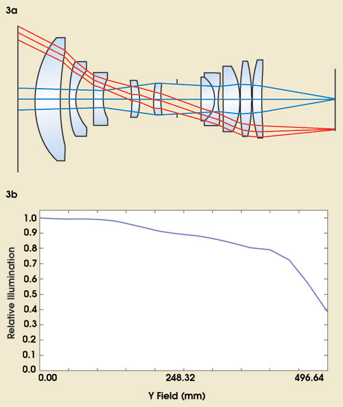
Figure 3. This schematic depicts a wide-angle camera lens with a center or chief ray bundle (blue) and an outer ray bundle (red) that is subject to vignetting (a). Calculation of the relative illumination of the displayed lens set shows an intensity drop of 70 percent at the edge of the imaged area (b). (Courtesy of Ingenieurbüro Klaus Eckerl.
A second source of vignetting in the lens is its view angle. The smaller this angle is, the more parallel the light rays guided though the lens system. In turn, the outer rays are less prone to the inner aperture cutoff.
The microlenses
To improve the sensitivity or quantum efficiency of image sensors with poor fill factor (the ratio of light-sensitive area versus the total area of a single pixel), chip manufacturers typically apply microlenses to the sensors. Poor fill factor is mostly a problem with CMOS and interline transfer CCD sensors. The microlenses focus the light onto the light-sensitive part of the chip, improving the quantum efficiency significantly.
For example, the sensor’s quantum efficiency without microlenses may be just 10 percent because of the small fill factor of the interline pixels, and with microlenses, the peak quantum efficiency could be as high as about 58 percent.
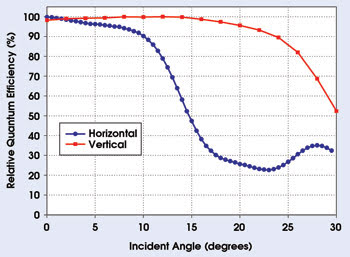
Figure 4. The angular dependence of the horizontal (blue) and vertical (red) quantum efficiency of a KAI-11000 interline transfer CCD image sensor is depicted. Courtesy of Eastman Kodak Co.
But there is another effect at play. If the quantum efficiency of the same sensor is measured under different incident angles (zero angle mean perpendicular to the surface of the image sensor), it can be seen that the microlenses reach a limit. At certain acceptance angles, they are not useful (Figure 4). This occurs because, if the incoming light’s angle of incidence fits the imaging characteristic of the microlens, the light rays are properly focused and hit the light-sensitive area, but if the angle of incidence becomes larger — such as with the use of a normal or wide-angle lens — the light rays are imaged outside the sensitive area and partially hit the nonsensitive part of the pixel (Figure 5). In addition, the geometrical layout of the image pixel causes the quantum efficiency to differ, depending on whether the change of incident angle is horizontal or vertical.
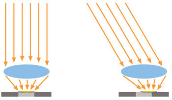
Figure 5. This schematic is a cross-sectional view of a microlens on top of a single pixel (dark- and light-gray areas). Left: the light-ray bundle (orange) hits the pixel under a view angle of 0°, or normal incidence (ideal conditions), and is focused onto the light-sensitive part of the pixel (light-gray insert). The image light spot (yellow ellipse) matches the light-sensitive part. Right: the light-ray bundle hits the pixel under a certain angle and is not totally focused onto the light-sensitive part of the pixel. The image light spot does not match the light-sensitive part.
But is there a cure for this shading effect? In fact, there are several. The simplest solution is to use a camera lens with a long focal length and a small aperture setting (f/8).
The intensity drop at the edge of an image using an f/8 aperture and a focal length of 200 mm is just about 10 percent, which is very good (Figure 6). The f stop limits the diameter of the light rays, and the long focal length reduces the view angle such that the inner aperture can be neglected and the microlenses can focus properly. In practice, though, this is not very useful because the camera must be positioned far from the event, and such imaging typically requires a great deal of light.
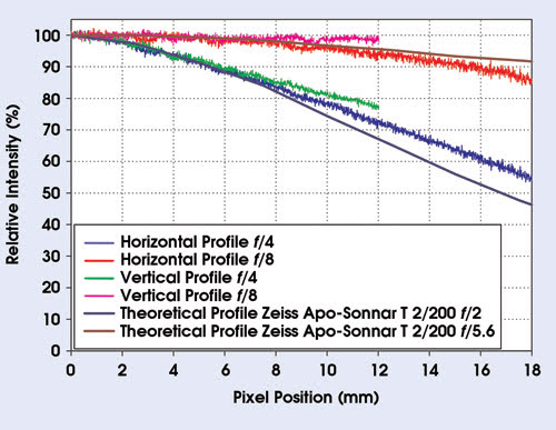
Figure 6. Images were recorded with a KAI-11000 interline transfer CCD camera. The imaged area was homogeneously illuminated, and images were recorded at different exposure times and f-stops with a Nikon 200-mm, f/4 lens. Center horizontal and vertical profiles were later extracted from the images and, for comparison, similar values were extracted from Zeiss lens product sheets.
A more practical solution is to use larger-format lenses, which exhibit less vignetting because of their larger image circles. Therefore, with F-mount sensors, the lenses would use the flatter part of the intensity curve. They can show significant improvement (compare Figure 7 with Figure 3b).
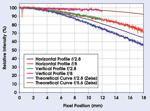
Figure 7. As with Figure 6, images were recorded with a KAI-11000 interline transfer CCD camera under homogeneous illumination, various exposuretimes and f-stops, but with a Zeiss 80-mm, f/2.8 lens. Center horizontal and vertical profiles were later extracted from the images and, for comparison, similar values were extracted from Zeiss lens product sheets.
Large-format lenses
Even though the horizontal profiles are still below the original manufacturer values because of the microlens effect, large-format lenses appear to be a practical solution. This approach does come at a high cost: The microlenses still have a significant effect when images are recorded with an open aperture (focal lengths smaller than 80 mm).
The third solution to reduce shading is to develop and construct new lenses. It is possible to create lenses that show only minor vignetting and that significantly reduce the shading effect (Figure 8). Recently, this type of lens was released by Ingenieurbüro Eckerl of Hutthurm, Germany, for 1-in. image sensors. Such lenses would solve most of the shading problems because the camera lenses themselves contribute to the majority of the problem. A 10 to 20 percent decrease in light at the edge of an image is easily corrected.
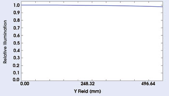
Figure 8. The image shows the result of the calculation of the relativeillumination of the displayed lens set with an intensity drop of 10 percent at the edge of the imaged area. Courtesy of Ingenieurbüro Klaus Eckerl.
For the future, these types of lenses would be needed to fully realize the benefits of large-format sensors, such as high dynamics, and of high resolution, providing greater detail at lower magnifications. They are typically larger, heavier and more expensive than standard F-mount lenses. Lenses under development for image sensors beyond 1 in. would offer the best performance.
Meet the author
Gerhard Holst is an electronics engineer and head of the research department at PCO AG in Kelheim, Germany; e-mail: [email protected].