Mark Browne, Andor Technology PLC
Since the first commercial
confocal laser scanning microscope (CLSM) was introduced more than 20 years ago,
it has become an essential tool for life sciences research, contributing to many
discoveries about cell and tissue structure and function. The key feature that sets
a confocal microscope apart from a conventional epifluorescence microscope is its
ability to acquire images of optical sections from the specimen. A series of optical
section images can be manipulated with computer software to produce high-resolution
3-D images. Computer analysis of these images reveals spatial and functional relationships
between discrete elements of the specimen. Sections can be very thin (approximately
1 to 5 µm), but because the technique interrogates optically, it is essentially
nondestructive.
During the same period, and spurred on by the availability of
increasingly sophisticated instrumentation and computing, scientists have invented
many techniques to label specific cellular components with fluorescent probes. Examples
include immunolabeling and genetic transfection, in which genes expressing fluorescent
proteins can be introduced into the DNA of host cells and organisms. These transfected
genes can be used as “optical reporters,” lighting up when the host
is “expressing” a specific genetic function. When this is done with
multicolored fluorescent probes, the confocal microscope can acquire data with exquisite
detail in 3-D, revealing structural and functional information. An example of such
a 3-D image is shown in Figure 1.
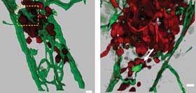
Figure 1. This example of a 3-D data set (and zoomed view, right)
was obtained with a confocal microscope. The raw data consists of optical sections
from a zebra fish embryo, which is used to study tumor cell morphology and metastasis.
Blood vessels are shown in green, while tumor cells are in red. The optical sections
have been rendered with Bitplane Imaris software to provide a surface rendering;
when time-series data is available, cell morphology and movements can be quantified.
Data courtesy of professor R. Klemke and colleagues, University of California, San
Diego.
The CLSM has been especially useful in the study of fixed specimens.
However, in the past 12 to 15 years, research focus has widened to include the study
of living cells. Studying time-sensitive events in live specimens requires monitoring
environmental conditions related to cell health as well as limiting light exposure,
to avoid phototoxicity and cell death. While CLSM has been applied to live cells,
its sequential scanning of the specimen is slower and more phototoxic than the parallel
illumination and detection approaches available with laser spinning disk confocal
(LSDC) microscopy,1 a technique that has been developed more recently.
CLSM and LSDC instruments both rely on high-performance laser
illumination, which is expensive and requires regular maintenance. This may make
it difficult for individual users and smaller laboratories to justify having it,
yet the need still exists for these labs to have direct access to equipment for
their studies outside of the “central imaging facility” model. Fortunately,
a recent development is set to change the cost-performance balance in this space
as manufacturers develop fast confocal instruments for rapid fixed and live-cell
imaging.
One such system is the first to successfully deliver high-performance
confocal imaging using a white-light source rather than lasers. The differential
spinning disk (DSD) scanner can provide multifluorophore imaging from a single light
source at a cost substantially lower than CLSM or LSDC instruments. However, unlike
previous white-light systems, a DSD offers performance that is comparable to that
of a point scanning system, but with higher speed and lower photobleaching.
The new Andor Revolution DSD, a structured illumination spinning
disk confocal scanner, uses a patented optical detection principle known as “aperture
correlation” to reject out-of-focus light.2
Key benefits of the DSD scanner include frame rates up to 10 times
those of point scanning systems; optical sectioning with objectives ranging from
10x to 100x; usability with many fluorophores by selection of appropriate filters;
and, as will be discussed, simultaneous acquisition of confocal and epifluorescence
images.
In a spin
DSD scanners differ from traditional CLSM and LSDC microscopes
because they scan a “structured illumination” pattern instead of one
or more laser beams (Figure 2). Structured illumination microscopy has been applied
before but has not been integrated into a commercial spinning disk system.
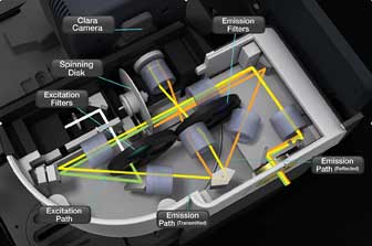
Figure 2. A solid model of a differential spinning disk confocal scanner shows a schematic
of the optical path. The excitation beam is green, while the emission fluorescence
beams are shown in orange and yellow to illustrate the different optical paths of,
respectively, the reflected and transmitted signals. The two signals are combined
at the prism and projected onto two sides of the camera.
Spinning disk systems in general are much faster than point scanners
because they scan the specimen illumination pattern in parallel. This illumination
pattern induces in the specimen fluorescence that is captured by a sensitive CCD
or electron multiplying CCD camera system. Further, CCD and electron multiplying
CCD detectors commonly have photon conversion (quantum) efficiencies on the order
of 60 to 90 percent.
In contrast, CSLM point scanners are sequential illumination and
detection systems usually employing photomultiplier tubes, whose quantum efficiencies
are in the range of 20 to 30 percent. Moreover, sequential beam scanning means that,
because the beam is scanned faster, less time is spent on each part of the sample.
Thus, for the fluorophore to return enough signal to form an image, illumination
intensity must be increased.
Initially, intensifying the light excites more fluorescent labels
and increases the amount of fluorescence emitted. However, at a certain point, all
the fluorescent labels are in their excited state, and intensifying the light further
will not generate any additional fluorescence. This means that the laser scanning
speed cannot be increased further without decreasing the image quality.
In a DSD system, the spinning element comprises a single synthetic
quartz disk supporting a thin layer of aluminum in which the structured illumination
pattern (SIP) is created by photolithography. The aluminum SIP has a 1:1 mark to
space ratio (half metal and half space), which means that approximately half of
the light falling upon it is reflected (R), while half is transmitted (T) (Figure
3).
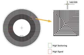
Figure 3. The differential spinning disk is manufactured with two structured illumination
patterns, radially disposed. In the Andor differential spinning disk, the inner
pattern, referred to as the “high signal” region, is designed with a
320-μm pitch and a 1:1 mark-space ratio. The outer pattern, referred to as
the “high sectioning” pattern, has a 160-μm pitch. The smaller
the pitch, the sharper the axial response or “optical sectioning” capability.
These patterns have been found to deliver a good compromise between optical sectioning
and signal-to-noise ratio.
The disk is located at an image plane of the microscope optical
system, so that an image of the SIP is projected into the specimen, and about half
of the illumination intensity arrives at the specimen, while the remainder is reflected
back into the illumination pathway, where it is baffled to minimize background.
In the detection pathway, the resulting fluorescence signal comprising what is in
focus (confocal, or C) and out of focus (wide field, or WF) is imaged back onto
the disk, where we make use of its transmissive and reflective properties.
Getting into focus
The fluorescent light transmitted by the DSD comprises the C signal
plus about half of the WF signal, while the light reflected from the disk comprises
about half of the WF minus the C signal. In confocal terminology, the SIP is located
in a conjugate image plane and hence acts as both the confocal source and the detection
apertures. However, as it is not a pinhole, we must undertake some further image
processing to separate confocal and wide-field signals. The optical path is illustrated
in Figure 2.
From the description above, we can see that the transmitted and
reflected signals can be approximated as follows:
T = 0.5WF + C; R = 0.5WF — C (Equation 1)
and simple algebra shows us that
2C = T — R; WF = T + R (Equation 2)
As Equation 2 highlights, we need to collect both transmitted
and reflected light signals (images) to compute the confocal signal. Furthermore,
we can easily compute the wide-field (conventional epifluorescence) signal as well
as the confocal.
Bear in mind that the simple mathematics of Equations 1 and 2
hides one complexity in the principle of the DSD; i.e., the T and R images must
be well-registered for the calculations to provide high-quality images. Any misalignment
between the two will result in registration noise, so an essential feature of image
processing for the DSD is a high-performance, real-time registration algorithm.
The SIP pitch is comparable to the pinhole size in a conventional
confocal scanner. Its dimension (as well as the microscope objective properties
and imaging wavelength) determines the resulting optical section thickness, but
the similarity ends there, because the DSD confocal image results from an image
processing operation that actively subtracts the wide-field signal. The result is
that the DSD achieves high contrast even at low magnification with relatively thick
optical sections. In addition, it should be pointed out that, although the SIP has
been simplified to an array of linear features (as shown in Figure 3), the DSD performance
is far superior to that of a slit scanning confocal. A recent publication shows
that active rejection of wide-field signal delivers a sharper roll-off in the axial
response compared to a point scanning instrument.3
DSD compares well to CLSM with respect to photobleaching, a nonlinear
effect in which high illumination power has the greatest effect. Photobleaching
leads to toxicity in live specimens and loss of signal over time. LSDC is known
to provide lower bleaching by virtue of parallel illumination and detection: The
laser is expanded to create about 1000 individual beams for scanning. DSD yields
bleaching performance similar to that of LSDC with roughly 100 SIP lines being scanned
in parallel with a similar illumination power per unit volume.
On the other hand, because DSD must detect confocal signal in
the presence of the much larger wide-field signal, its signal-to-noise ratio is
constrained by the wide-field shot noise. Shot noise-limited signal-to-noise ratio
means that signal must be traded with optical sectioning. Very thin optical sections
result in a poor signal-to-noise ratio; hence DSD SIP design is intended to optimize
the trade-off (Figure 3).
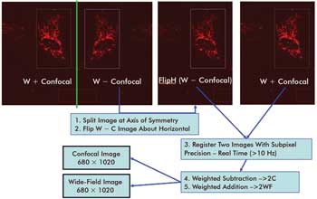
Figure 4. Illustrated
is the image processing flow used to register and combine the T and R images as
defined in Equations 1 and 2. On the top left of the figure is the raw image collected
by the camera. On the top right are the flipped WF — C and WF + C images that must
be registered to high precision. Addition of the resulting image pair yields the
WF image, while subtraction produces the C image. Because addition and subtraction
are very fast compared to the registration step, both C and WF images can be obtained
for little overhead and almost simultaneously.
Because the DSD system collects and separates wide-field and confocal
light, it is possible to switch between the two with a simple click in Andor’s
iQ control software (Figure 4). This can be very helpful when bringing the specimen
into focus – a major advantage because focusing on a specimen can be difficult
with a conventional spinning disk or point scanner. An image of a fixed specimen
acquired with an Andor Revolution DSD system is shown in Figure 5, where wide-field
and confocal images are shown side by side.
Many factors must be considered when choosing an instrument for
scientific research. DSD-based systems will not replace CLSM or LSDC in all conditions,
but they do represent a viable alternative in many applications ranging from analysis
of fixed tissue to live-cell imaging. DSD can be tuned to a broad range of fluorophores,
operates at high and low magnification, and acquires full-resolution images at frame
rates on the order of 1 to 10 Hz.
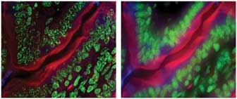
Figure 5. Three-color images of a fixed specimen were acquired with an Andor Revolution
DSD system. On the left is an extended-focus confocal image exhibiting high clarity
and spatial resolution, low background and lack of out-of-focus blur. On the right
is the equivalent wide-field image (acquired simultaneously) with the characteristic
limitations of epifluorescence imaging.
Developing a high-quality white-light confocal system has been
a goal for many companies because of cost and maintenance benefits over laser-based
instruments. However, until recently, such systems delivered unacceptable image
quality for all but a few applications.
DSD scanners deliver a solution to these limitations and change
the confocal landscape from the user’s perspective. DSD provides image quality
comparable to that of laser point scanners at moderate light levels.
Meet the author
Mark Browne is director of the systems division at Andor Technology
plc; e-mail: [email protected].
References
1. E. Wang et al (May 2005). Performance comparison between the
high-speed Yokogawa spinning disc confocal system and single-point scanning confocal
systems. J Microsc, pp. 148-159.
2. R. Juskaitis et al (October 1996). Efficient real-time confocal
microscopy with white light sources. Nature, pp. 804-806.
3. V. Poher et al (August 2008). Improved sectioning in a slit
scanning confocal microscope. Opt Lett, pp. 1813-1815.