Dr. Victor I. Kopp, Dr. Azriel Z. Genack, Dr. Victor M. Churikov, Jonathan Singer and Norman Chao, Chiral Photonics Inc.
Chiral photonic devices have a screwlike, or helical, microstructure with a period comparable to the optical wavelength, which enables them to control or manipulate light. Chiral fiber gratings are produced by twisting fiber with a noncircular fiber core as it passes through a miniature oven.1 These structures occur naturally in right- or left-handed forms, depending on the direction of twist. Because they do not have mirror symmetry, they interact differently with right and left circularly polarized light.
Chiral structures also may be found in planar forms, such as cholesteric liquid crystals, which occur in nature or which can be synthesized via self-organization, and in sculptured thin films, which are produced by oblique deposition of dielectric materials on a rotating substrate.2,3
The structures are composed of birefringent planes with birefringent axes that lie within the sample planes. They rotate with a constant pitch P about an axis perpendicular to the planes. As a result of the 180° rotation symmetry in each plane, these structures have double-helix symmetry with P = 2a, where a is the structure period.
Because these helical structures have a sinusoidal index variation, only a single reflection band exists. Co-handed light, with the same sense of circular polarization as the twist of the structure, is resonantly reflected within a stopband. This covers the range of vacuum wavelengths over which λ, the wavelength in the structure, is equal to the pitch, λ = λvac /neff = P, where neff is the effective index of refraction. Cross-handed light with an opposite sense of circular polarization is freely passed by the structure. The width of the reflection band in vacuum wavelength is Δλvac = PΔn/<n>, where Δn is the birefringence. This is the difference in effective index of refraction for linearly polarized light aligned along the slow and fast axes of the fiber, and <n> is the average of these effective indices.
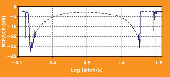
Implementation of the double-helix symmetry into a fiber geometry4 can expand its functionality in telecommunications and sensor applications. To examine the optical interaction of core modes within chiral fibers, Chiral Photonics Inc. of Clifton, N.J., measured polarized microwave and optical transmission through the chiral fiber gratings over a wide range of the parameter Q = P/λ (Figure 1).

Figure 1. This plot illustrates the performance of a chiral fiber grating (shown is the ratio of right to left circularly polarized transmission vs. Q = Pλ). Data for small values of Q covering the resonant bandgap and the long-wavelength side of the nonresonant scattering gap were obtained from measurements of microwave transmission through a chiral rod. Results at the short-wavelength side of the nonresonant band and at larger values of Q were obtained from measurements of optical transmission. The dashed line connects the spectral ranges in which experimental results were obtained.
In the intermediate portion of the plot from Q ~1.25 (log(Q) ~0.1) to Q ~45 (log(Q) ~1.65), the chiral grating selectively scatters co-handed radiation out of the fiber at angles that range from near the backward to near the forward directions, respectively. In the middle of this gap, it is expected that scattering is nearly normal to the fiber and independent of polarization.
There are resonant regions on either side of the nonresonant intermediate scattering gap. In the stopband at Q = 1 or P = λ (log(Q) = 0), the co-handed light reflects back through the fiber core. At much greater values of the pitch, P ~ 80λ (log(Q) ~1.9), co-handed light will resonantly couple to co-propagating cladding modes, producing multiple narrow dips in the transmission spectrum, similar to those in standard fiber long-period grating.

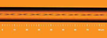
Figure 2. This is a side view of a chiral fiber grating with excellent periodicity. The structure was produced using specially designed fiber preforms with a noncircular core cross section.
The most practical range for polarizer applications is near Q = 45 (log(Q) ~1.65). An extinction ratio of greater than 30 dB — with an insertion loss dominated by the quality of the splice of the polarizer to its pigtails — is possible over a spectral range of more than 100 nm. Chiral gratings represent an alternative to fiber Bragg gratings (Figure 2). Because this fiber is created without the photosensitive glass used in standard fiber Bragg gratings, the polarizers can serve in extreme environments in which the need for sensors is critical.
Meet the authors
Victor I. Kopp, Azriel Z. Genack, Victor M. Churikov, Jonathan Singer and Norman Chao are researchers with Chiral Photonics Inc. in Clifton, N.J.; e-mail: [email protected].
References
1. V.I. Kopp et al (2004). SCIENCE, Vol. 305, p. 74.
2. S. Chandrasekhar (1977, 1994). Liquid Crystals. Cambridge University Press, Cambridge.
3. K. Robbie, D.J. Broer and M.J. Brett (1999). NATURE, Vol. 399, p. 764.
4. V.I. Kopp and A.Z. Genack (2003). Double-helix chiral fibers, OPT. LETT., Vol. 28, p. 1876.