Designing an observatory that will travel a million miles from Earth to study the first light requires a special class of photonic instruments.
Hank Hogan, Contributing Editor
In 2013, the James Webb Space Telescope is scheduled for launch. Three months later, it will settle into a spot about 1 million miles from Earth, from which it will record light from nearly the beginning of time and from the edge of space. By collecting photons in the dark at cryogenic temperatures, the instrument might answer questions about how the universe came to be and how life originated.

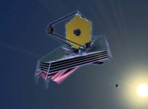
In an artist’s rendering of the James Webb Space Telescope, a 6.5-m-diameter mirror is deployed with a multilayer sun shield that helps ensure cryogenic operating temperatures. The observatory will be positioned ar the L2 Lagrangian point ~1 million miles from Earth. Courtesy of Northrop Grumman.
To accomplish these goals, 10 enabling technologies first had to be developed. Although the telescope has yet to fly, those technologies recently passed important tests, proving that they are operational under conditions simulating the telescope’s space environment, according to John E. Decker, deputy associate director of the telescope project at NASA’s Goddard Space Flight Center in Greenbelt, Md. “[The technologies] reached a certain level of maturity as codified within the NASA guidelines. We made that milestone.”
Among the enabling technologies are the main mirror and the wavefront sensor — which enables the segmented mirror to work as if it were one piece — extremely sensitive detectors that span from red to thermal wavelengths, and microscopic shutters that permit 100 spectrograms to be collected simultaneously.
Mirror alignment
As with other large telescopes, the 6.5-m-diameter light-collecting area in the space telescope is divided into mirrored sections — in this case, 18. The sections are made of a form of beryllium of a higher purity than has been used before, according to Scott Texter, the telescope manager at Northrop Grumman Space Technology in Redondo Beach, Calif. Starting out at 600 lb, each section is machined down into a 45-lb segment with a polished surface that must fit the required curve precisely, so that it yields the expected optical performance.
Texter explained that the instrument is designed to be diffraction-limited at a wavelength of 2 μm. Leaving room for various error sources drives the required fit for the surface down to 20 nm. The total mirror mass is half that of the one in the Hubble Space Telescope, whereas the collecting area is nearly six times larger. Consequently, the mirror must be lightweight, which, in turn, means that the designers must account for the effects of gravity and temperature. The segments are constructed on Earth in such a way that they will have that perfect shape when in orbit.
“We have to, in effect, deliberately bias-figure them so that, when they go out into space and gravity is released, they spring into the correct shape,” Texter said.
Similarly, the surface is finished at room temperature but will operate at ~35 K. Changes in the beryllium shape brought about by the temperature difference also must be considered when finishing the mirror.
The total light-collecting area is brought into alignment via actuators that move the segments into place and wavefront sensing that determines where they should be moved. Lee D. Feinberg, optical telescope element manager for the project at Goddard, noted that similar alignment technology has been used elsewhere. There are, however, some key differences.

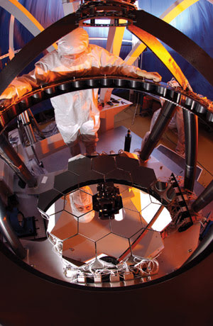
The 1/6-scale optical test of the space telescope’s mirror and other elements built by Ball Aerospace & Technologies Corp. of Boulder, Colo., was used to verify the wavefront sensing and control as well as other critical subsystems. Courtesy of Northrop Grumman. Tests conducted on the telescope’s multilayer sun-shield membrane material have verified its design. Now the full-scale sunshade model undergoes folding and deployment trials to prove that the system works. Courtesy of Northrop Grumman.
First, because the instrument will sit behind a sun shield in orbit, it will not undergo much in the way of thermal or other changes. Therefore, the telescope will not need to have its shape corrected often after the initial alignment; plans call for realignments to take place every two weeks. Second, the designers opted to do the necessary wavefront data capture without adding the weight and complexity of edge- and dedicated-wavefront sensors — devices used in other instruments. The wavefront sensing necessary for corrections will be accomplished using defocused images from the main science camera and the known characteristics of the instrument.
“There is a relationship between an image taken at the detector and the primary mirror,” Feinberg said.

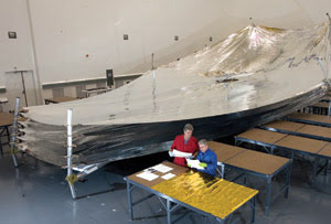
Tests conducted on the telescope’s multilayer sun-shield membrane material have verified its design. Now the full-scale sunshade model undergoes folding and deployment trials to prove that the system works. Courtesy of Northrop Grumman.
With that information, the actual defocus change can be compared with the predicted one, and the actual shape of the mirror can be uncovered. It is an iterative and computationally intensive process, but it can be done quickly by computers on the ground.
Infrared imaging
The space telescope’s designers employed a sun shield, orbital position factors and careful attention to the device’s own heat production to keep the instrument at cryogenic temperatures. That makes some design aspects a bit more challenging but also helps the instrument’s detectors operate with an unprecedented sensitivity. The detectors fall into two categories: near-infrared devices that operate from 0.6 to 5.0 μm and mid-infrared ones that operate from 5 to 29 μm.
The near-IR imagers are made by Teledyne Scientific & Imaging LLC of Thousand Oaks, Calif. They have 2048 × 2048 pixels and are made with mercury cadmium telluride chips with thinned substrates that help avoid cosmic ray scintillations and allow the devices to operate down to 600 nm.
Besides their large size and their wide spectral response, the detectors have innovations that will allow them to run at a state-of-the-art noise level. According to Goddard’s Bernard J. Rauscher, principal investigator of near-infrared spectrography for the project, the detectors have a noise level of 6 e– per pixel during 1000 s of integration, a performance made possible only with the use of reference pixels, which are blind to light but otherwise operate like any other pixel.
“The [reference pixels] have been designed to electrically mimic a regular pixel. What they allow us to do is subtract any drift in the electronics,” Rauscher said.
Armed with that information, software can remove drift effects, enabling the sensor to collect data for a longer time and allowing a longer exposure that will reveal dimmer objects. The detectors also have special chips that isolate sensitive circuitry and, therefore, further protect against electronic noise.
In general, sensors that respond to longer wavelengths must be operated at colder temperatures. For the near-IR detectors, the ambient temperature of the telescope will be cold enough. That is not the case for the longer-wavelength detectors, which must operate at 7 K and, therefore, must be chilled via a cryo-cooler system being developed by Northrop Grumman.
Michael E. Ressler is a project scientist for the mid-IR instrument at the Jet Propulsion Laboratory in Pasadena, Calif. He said that the 1024 × 1024-pixel sensors are As:Si impurity band conductors manufactured by Raytheon Vision Systems of Goleta, Calif. The primary reason for cooling them is to minimize dark current, which increases by an order of magnitude with every increase of 1 K. Thus, keeping the detectors as cold as possible is mandatory.
Another performance-related reason is that investigators want them to be limited by thermal emission from dust in the solar system or from the rest of the instrument — not by the heat of the detector itself. “We need to make sure that we are colder than everything around us,” Ressler said.
As with the near-IR sensors, the detectors have reference pixels, blind elements with signals that travel through the same video amplifiers as do active pixels. The mid-IR sensors also have circuitry for common mode rejection to further reduce noise and to maximize the signal-to-noise ratio.
Tiny shutters
The final enabling technology for the telescope is quite small but has an immense effect on the instrument’s productivity: 100 × 200-μm shutters. Arranged in a wafflelike grid comprising more than 64,000 elements in each of four quadrants, the “microshutters” were developed by a team at Goddard. When closed, they block light falling on a spectrographic instrument; open, they allow light through selectively.

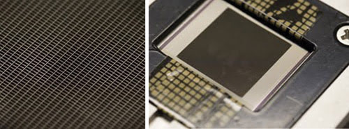
Arranged in a wafflelike grid, individually addressable 100 × 200-μm shutters enable researchers to capture the spectra of faint items of interest while blocking the light from brighter objects. Courtesy of NASA.
Behind the development and deployment of this innovation is a desire to accomplish more with every field of view available to the telescope. A deep-field image acquired with the instrument will have in it hundreds or even thousands of galaxies and other objects of interest, each one taking up only a small part of the total field of view. “We wanted to have the capability to — in a single image of a field — take spectra of up to 100 objects,” said Goddard’s Decker.
He added that, on the ground, a mask would be constructed to handle such a situation — an approach impossible in an automated observatory a million miles away. With the individually addressable microshutters, however, researchers can open those that align with a target, capturing its near-IR spectra on mercury cadmium telluride sensors. Because the microshutter provides a hole in an otherwise opaque covering, the technique imparts a good contrast ratio between those pixels capturing the signal and those in the dark. In case the shutters fail, the instrument also has some fixed slit openings that can be used for high-contrast spectroscopy.
The microshutters, detectors, wavefront sensors and mirrors — as well as other advanced technologies — have passed all tests by working in a vacuum at cryogenic temperatures and by meeting rigorous specifications. That, Decker noted, is a significant accomplishment and an advancement of the state of the art — long before the telescope begins its work. “Those things [are] needed to exist in order for us to do this mission, and they did not exist before people started thinking about this mission.”
James Webb Space Telescope Fast Facts
Launch: 2013.
Location: 1.5 million km from Earth at second Lagrangian point.
Wavelength: visible to infrared, 0.6 to 29 μm.
Mirror diameter: 6.5 m.
Instruments: near-IR camera and spectrograph, mid-IR instrument, tunable-filter imager.
Science goals: study first galaxies, large galaxy assembly, the birthplace of stars and the evolution of planetary systems.
Collaborating organizations: NASA, European Space Agency, Canadian Space Agency.
Source: NASA; www.jwst.nasa.gov
Sunshade, ‘Sunjammer’
Photons do not have mass, but they do exert force. The radiation pressure from sunlight on Earth amounts to only a few micro-pascals per square meter — much too feeble for anyone trying to get a tan to notice. However, the James Webb Space Telescope cannot ignore the push of light.
The instrument is designed to operate at a balancing point between the Earth and sun, remaining at a fixed location relative to both. Staying at this spot, called the second Lagrangian point, or L2, enables the device to capture long exposures of light for distant stars; thus, the spacecraft will carry fuel to counter the tug of the moon and planets.
Complicating matters, though, is the instrument’s sun shield, a five-layer, thin-membrane polymer film that measures 40 × 65 ft. According to Scott Texter of Northrop Grumman Space Technology, some 100 kW of sunlight will fall on the shield, but only about 10 mW will make it through to the instrument. Most of the light will be reflected instead, doubling the radiation pressure on the spacecraft. Thus, some fuel will have to be expended to counter the force of sunlight.
In addition, because the sun shield will not be aligned perfectly with the spacecraft’s center of gravity, light pressure will create torque. The shield has trim tabs that, on average, attempt to balance out any torque, but they cannot completely cancel the effect. To help, the telescope has a momentum-unloading system, a set of wheels that spin to either store or release momentum. Most of the momentum change will arise from moving the telescope around to various parts of the sky. Some, though, will be from the pressure on the sun shield.
Texter noted that the force of sunlight has been taken into account in designing the instrument. “That is actually a pretty complex calculation, with respect to determining the maximum amount of fuel to maintain the observatory over its mission life.”