Dr. Martin A. McMahon, Melles Griot
Coupling a single-mode fiber to the lens of an infrared diode laser is one of the most common optical fiber alignment tasks. The success of this pigtailing process depends on accurate manipulation of the fiber in the X-, Y- and Z-axes, typically to within 20 nm. Depending upon the manufacturing and fixturing tolerances of the components, adjustments in yaw, pitch and roll may also be required.
In this application, successful alignment requires careful balancing of factors such as the total cycle time, the acceptable level of alignment failures when using good components, the abandonment time tied to use of faulty components, the alignment tolerances and the optical coupling efficiency. The main criterion, however, is the ability of the alignment system to perform the same operation repeatedly with precision and consistency. Flexure-stage technology combined with process automation can meet this need.

Parallel flexure stages can deliver high resolution and repeatability in both linear and rotational axes of motion.
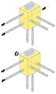
Flexure stages are based on the principle that certain materials, when deformed elastically, will return to their original state when the deformation force is removed (see figure). In a six-axis flexure stage, for example, a single moving platform is tied to six flexures, each, essentially, a rigid rod with a flexible coupling at each end that provides two degrees of freedom. Linear actuators are attached to the free end of each rod. By pushing or pulling the rods in pairs, the stage provides six degrees of freedom.
Compared with multiaxis bearing stages, flexure stages — such as the NanoMax 600 from Melles Griot —have several distinct advantages: They are virtually free from friction and stiction, are relatively low in profile, and avoid the buildup of errors and loss of stability caused by stacking individual stages. However, they are limited to a few millimeters of travel and, thus, for pigtailing fibers, are used only in the final alignment steps. Less accurate, longer-travel carriers can be used for operations such as load and unload.
Automation of pigtailing
Programming an automated system for a typical pigtailing application is increasingly easier to do, thanks to flexible software tools. The alignment process typically comprises the following steps:
• Loading the components by driving the fiber and laser holders far apart.
• Moving the stage platform with the fiber holder to a predetermined start position in front of the laser module with a gap setting of less than 100 μm.
• Obtaining threshold laser throughput (first light) through the fiber using a motorized spiral scan in the plane transverse to the optical axis. The autoalignment controller then takes over.
• Optimizing the light coupling in the plane (X-Y) transverse to the optical axis.
• Optimizing the light coupling along the optical axis (Z) by moving the fiber closer to the laser (toward the focal point). As the focus is passed, the power declines, and the optimum position can be defined.
• Freezing the fiber at the optimum position.
The motor search for first light can take from a few seconds to a minute, depending upon the optical tolerances of the components, but the resulting prealignment of the components in all three axes is typically better than 20 μm. Final alignment with an autoalignment controller typically brings the components to within a few nanometers of optimum. Ultimately, though, successful alignment also depends on other factors, such as the output characteristics of the individual device and even the software application used to control the sequence of events.
Because a controller — for example, the NanoTrak — is a phase-sensitive device (a bit like a lock-in amplifier), it is highly sensitive to signals modulated at its own scanning frequency. The higher the scan rate is, the quicker the alignment. However, because it is a feedback system, its stability is sensitive to loop gain and phase. Consequently, it may be necessary to fine-tune controller settings to add phase-angle compensation or to adjust signal gain. Incorrect selection of these parameters can lead to instabilities and a failed alignment, which is why control software is a critical component of the alignment system.
Increasingly, graphical user interfaces are providing the infrastructure required for building custom applications. For example, system configuration often can be accomplished using a server application based upon ActiveX components. Customizing an alignment application is only a matter of controlling the methods associated with each component. A well-written application based on this technology can run faster and more efficiently than those typically associated with dynamic-link libraries. End users also can access open-source program examples to aid in application development.
With a well-designed positioning system, an automated alignment setup can complete an optimized three-dimensional alignment in less than a minute, much faster than conventional automated or manual alignment systems.
Meet the author
Martin A. McMahon is senior product manager for nanopositioning products at Melles Griot in Ely, UK; e-mail: [email protected].