New software addresses the overlooked needs of optomechanical engineers by helping them package, analyze and validate new designs, simplifying the transition between optics design and packaging.
CORT STINNETT and TERESA TAYLOR, ZEMAX LLC
From cellphone cameras to space telescopes, driverless cars to the laser interferometer at LIGO (Laser Interferometer Gravitational-Wave Observatory), optics are transforming our lives. Optical system design and the optical engineer’s toolbox have evolved over the last two decades accordingly. What used to take optical engineers months to create can now be designed in a matter of hours or days. Using optical simulation software, optical engineers can design optical systems that weren’t possible two decades ago.
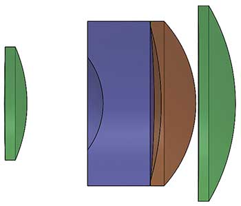
Figure 1. A 25-mm lens design in free space. Courtesy of Zemax LLC.
Although the toolbox for optical engineers has expanded to drive innovation and meet today’s challenges, optomechanical engineers have been left far behind, without the tools to address even basic problems. Further, optical engineers and optomechanical engineers address different challenges. Optical engineers use simulation software to lay out a lens system, essentially creating lenses and components in “free space.” They design the shapes and determine the positions of the lenses, mirrors, prisms, gratings and other optical components to achieve a given performance goal and to meet design specifications.
In contrast, optomechanical engineers design and build the packaging for the lens design. They are concerned with the materials, finishes, thermal design, stress, vibration, tolerancing, manufacturability, cost to manufacture and other considerations that may affect the optical performance or the success of the product. They must also design for brand consistency and user experience, such as the industrial design, weight, look and feel, and durability.
Inefficient workflow
In addition to addressing different challenges, optical and optomechanical engineers work in different design environments and speak in different languages; the process workflow between them is inefficient and cumbersome. In most cases, optomechanical engineers receive an exported STEP or IGES file in a computer-aided design (CAD) program from an optical simulation package. These “data blobs” do not include optics design files or data about the components or clear aperture location.
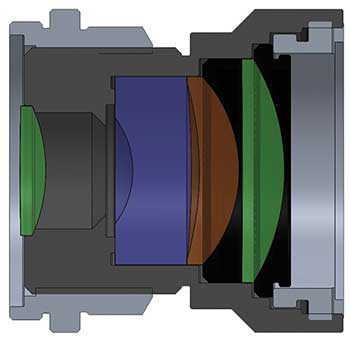
Figure 2. The same 25-mm lens design fully packaged. Courtesy of Zemax LLC.
Optomechanical engineers must manually rebuild the optical system within the CAD package, which is time-consuming and can introduce errors. For a complex optical system such as a telescope with many lenses, rebuilding the optical components in a CAD program can take days or weeks.
After importing and rebuilding the optical components, optomechanical engineers can start building the mechanical geometry and analyzing their design. However, there are no tools to help them assess the impact of their design on the optical system. They must either export the design back to the optical engineer to validate the design or build physical prototypes to assess the product’s performance.
The cycle of prototype and redesign can be repeated many times before the optomechanical design is finalized. These repeated design iterations increase costs, create stress within the design team and delay time to market. They also negatively impact the optical engineer, who typically works with several optomechanical engineers at one time. Validating each optomechanical engineer’s designs (often multiple times) creates a bottleneck in the workflow and a high opportunity cost for the organization by reducing the amount of time the optical engineer could spend developing new optical systems for the market.
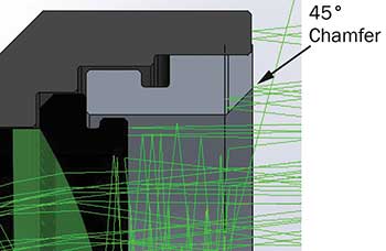
Figure 3. The 45° angle of the chamfer introduces stray light. Courtesy of Zemax LLC.
Improving optomechanical product development
To equip optomechanical engineers with the tools they need to package, analyze and validate optomechanical designs, Zemax LLC has developed LensMechanix, a plug-in for the 3D CAD design software SOLIDWORKS from Dassault Systemes that enables optomechanical engineers to analyze and validate their designs using full multithreaded ray tracing. Data associated with the optical components is preserved, such as materials, coatings, surface radii, edges, wavelengths and clear aperture location.
LensMechanix also loads sources and detectors, and automatically creates the optical component parts with actual lens dimensions, eliminating the need for STEP and IGES files. Within minutes, optomechanical engineers can start building mechanical geometry from the dimensionally accurate optical components, and then run ray traces and perform surface power analysis to compare the optical performance in SOLIDWORKS with the original output.
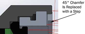
Figure 4. The stray light is corrected by changing the chamfer angle to a step. Courtesy of Zemax LLC.
Ray tracing capabilities make it easy for optomechanical engineers to discover and correct stray light contamination, beam clipping, image focus issues or other potential problems caused by the mechanical geometry — before they build a prototype or send the design to the optical engineer to review. A simple chart indicates “pass/fail” for image quality and stray light metrics. Detailed results data is also stored so that optomechanical engineers can troubleshoot the design or gather additional insights.
Stray light and beam clipping present challenges
Mechanical product development can degrade optical performance in many ways.
Two common problems are stray light and beam clipping. To demonstrate stray light and a possible solution, take a 25-mm single Gauss lens as an example. Stray light can be introduced into an optical system in many ways; even subtle changes to the mechanical geometry have a potentially major impact on optical performance. As shown in Figure 3, the 45° chamfer on the front retaining ring directs light onto the interior mechanical and optical surfaces. The reflected light propagates through the system, degrading the image quality. Changing the angle on the front retaining ring from a 45° chamfer to a small step or series of steps greatly reduces the amount of stray light entering the optical system (Figure 4).
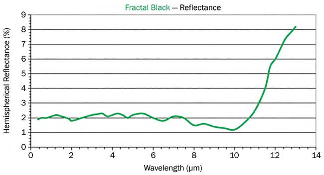
Figure 5. Reflectance vs. wavelength for Acktar’s Fractal Black coating. Courtesy of Acktar Ltd.
Applying an absorptive coating such as Acktar’s Fractal Black can help mitigate stray light. Absorptive coatings are optimized for specific wavelength ranges and must be matched to the optical system requirements. Acktar’s Fractal Black coating minimizes reflectance through a portion of the spectrum in optomechanical designs (Figure 5).
The best method of reducing stray light highly depends on the product under development. The optomechanical engineer must consider the manufacturing and assembly processes in addition to materials, finishes and cost.
Another common problem is beam clipping, which occurs when mechanical geometry interferes with light entering an aperture. The lens boundary that is intended for light to pass through is called the clear aperture (Figure 6).
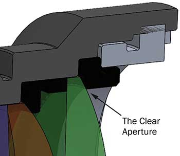
Figure 6. The location of the clear aperture on lens surface 1. Courtesy of Zemax LLC.
Any mechanical geometry that extends into the clear aperture will cause beam clipping. To evaluate beam clipping, today an optical engineer provides a ray bundle to the optomechanical engineer. A ray bundle file is the static ray trace output from the optical simulation package. Figure 7 shows an optical system imported with a static ray bundle.
As the mechanical packaging takes shape, the optomechanical engineer manually overlays the ray bundle onto the design to check that the rays do not hit the mechanical geometry. The static ray bundle, however, may not account for all of the mechanical geometry. When the mechanical packaging is large compared to the optical system, the optomechanical engineer must manually extend rays to account for all of the mechanical geometry. If the optomechanical engineer uses a fold mirror to change the direction of the light, it renders the new static ray bundle useless, and he or she must start over with a new design from the optical engineer.
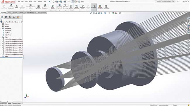
Figure 7. A STEP file imported with a static ray bundle. Courtesy of Zemax LLC.
New software can trace rays through an optomechanical system that has been modified with a fold mirror. It streamlines the workflow between optical and optomechanical engineers, who can collaborate efficiently while working in their preferred environments and formats. With the tools to validate their own designs, optomechanical engineers can eliminate repeated prototypes and extra development iterations, dramatically saving time for themselves and for optical engineers, improving collaboration, and speeding delivery to manufacturing.
Meet the authors
Cort Stinnett is general manager of the LensMechanix Division at Zemax LLC, which is headquartered in Kirkland, Wash.; email:
[email protected]. Teresa Taylor is communications manager of the LensMechanix Division; email: [email protected].