Researchers are working to perfect tunable dye lasers that are incorporated into microfluidic chips.
Nancy D. Lamontagne and Breck Hitz
Microfluidic technology has miniaturized many instruments used in biotechnology and medicine into devices about the size of a microscope slide. Developers of these devices, commonly called labs on a chip or biochips, want to achieve maximum miniaturization by incorporating as much as possible, including lasers and optics, directly onto the chip, and they want the devices to require a minimum amount of external power for maximum portability. Such devices could be useful in remote locations or right in a doctor’s office.
On-chip lasers must be easily and quickly tunable to allow spectroscopy or excitation at different wavelengths.
In one recent advance, researchers at Harvard University and at Massachusetts Institute of Technology, both in Cambridge, designed and operated a microfluidic waveguide dye laser in which the waveguide was created by the laminar flow of fluids with two different refractive indices. Although similar lasers have been demonstrated, this one exhibited a long optical path length along the waveguide axis, which allowed the researchers to achieve high gain in one pass and to lower the threshold for lasing. A lower threshold means that less power is required.
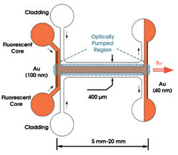
Figure 1. The waveguide in this microfluidic laser was created by the laminar flow of fluids with two different refractive indices. Reprinted with permission of the Journal of the American Chemical Society.
The device is detailed in the Journal of the American Chemical Society on June 29. It contained a 400 3 100-μm microfluidic channel, in which the high-index stream containing the gain material was enveloped within two low-index streams (Figure 1). The fluids entered the channel at one T-junction, flowed through and exited at another T-junction. Thin gold coatings on the surfaces of the T-junctions served as laser mirrors, a 100-nm-thick layer as the back mirror and a 40-nm-thick layer as the output coupler.
In their initial experiments, the scientists used rhodamine 640 perchlorate dissolved in methanol as the core stream and pure methanol as the cladding stream. They optically pumped the laser with a 532-nm frequency-doubled Nd:YAG laser at 50 Hz and observed that the bandwidth decreased by an order of magnitude at laser threshold (Figure 2). The sharp increase in output vs. input slope that they observed provided further evidence of lasing.
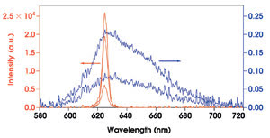
Figure 2. The emission bandwidth of the microfluidic laser narrowed by more than an order of magnitude at laser threshold. Note that the prethreshold scale is reduced by a factor of 105 from the postthreshold scale. Reprinted with permission of the Journal of the American Chemical Society.
Tuning the laser
Large dye lasers are typically wavelength-tuned by adjusting an intracavity grating or other dispersive element to tune the wavelength of the resonator. Such an approach, with its large, awkward wavelength-tuning element, is not desirable in a microfluidic laser.
As an alternative, the researchers tuned their microfluidic laser by changing the fluid flowing in the channel. Rhodamine 640, for example, lased at 617 nm when dissolved in methanol, at 631 nm in ethylene glycol and at 634 nm in dimethyl sulfoxide. They could tune the laser continuously by varying the composition of the mixed solvent (methanol-dimethylsulfoxide) while using the same concentration of the dye. Switching to a different dye should also be straightforward with microfluidic setups.
“The advantage of a liquid core-liquid cladding setup is that it allows real-time, dynamic tunability in laser characteristics (emission wavelength, efficiency, divergence),” Brian T. Mayers of Harvard said. Also, because the laser emits in the plane of the chip, its output can be coupled directly into other on-chip components without the fiber coupling that would be required if the laser were to emit perpendicular to the chip.
The laser design achieves high gain with fewer passes through the cavity and uses a liquid core-liquid cladding waveguide to direct light between the mirrors, so the requirements for alignment and quality of the mirrors also are reduced, he said.
In general, it would be desirable to have a microfluidic laser that is electrically pumped, Mayers said, but optical pumping is acceptable in many cases. By lowering the threshold to lasing in these microfluidic lasers, the researchers have made it possible to optically pump them employing, for example, inexpensive solid-state lasers, which can reduce the footprint of the whole setup, making it more portable.
In another solution for miniaturizing lasers, investigators at the Laboratorie de Photonique et Nanostructures, CNRS, in Marcoussis, France, have developed a miniature dye laser with a wavelength that can be quickly tuned by adjusting the microfluidic parameters of the flowing dye.
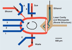
Figure 3. Dye is peristaltically pumped around the microfluidic loop (red) when the three valves (1, 2 and 3) are actuated successively at a given frequency. The concentration of the dye in the loop can be altered by manipulating the three input and output valves (A, B and C). Reprinted with permission of Applied Physics Letters.
The 5-mm-square laser uses a peristaltic pump to circulate dye through the resonator (Figure 3). The resonator is formed by four air slots in the SU-8 polymer from which the laser is fabricated. Light impinging on the slots is totally internally reflected, and the four air slots serve as the four mirrors for a ring resonator (Figure 4). A dye-flow channel passes through the center of the resonator. One of the air slots is connected to an injector so that it can be filled with ethanol. Because the refractive index of ethanol frustrates the total internal reflection at this mirror, it serves as the output coupler. The output of the clockwise-circulating light in the resonator is coupled into an output waveguide. Although the researchers have not measured it, they assume that the output of the counterclockwise-circulating light becomes lost in the chip.
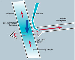
Figure 4. The laser resonator, shown on the right side of Figure 3, is formed by four air slots that act as total internal reflection mirrors. One slot can be filled with ethanol, which frustrates the total internal reflection and converts that mirror into the output coupler. Reprinted with permission of Applied Physics Letters.
Uses different dyes
They designed the laser to exploit two key advantages of microfluidic dye lasers. First, because such a small volume of dye is employed, one dye can easily replace another so that multiple wavelength ranges can be accessed. And second, because the output wavelength depends on dye concentration, the wavelength can be tuned by altering the concentration. The researchers did this by manipulating the valves controlling ethanol and dye input, waste extraction and the peristaltic pump (Figure 3).
To characterize the fluid dynamics of the chip, the researchers injected a small volume (~1 nl) of fluorescein into the loop and measured its fluorescence at a particular location on the loop. The intervals between observed fluorescence peaks equal the time it takes for the fluid to make one round-trip of the loop and allow calculation of the flow velocity (Figure 5). Also, the damping time of the sinusoidal oscillation is equal to the mixing time of fluids in the loop. From data similar to that presented in Figure 5, they calculated the flow rate in the loop as a function of the frequency of the peristaltic pumps.
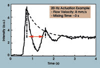
Figure 5. The researchers measure the fluorescence at a given point on the dye-flow loop when a tiny amount of fluorescein is injected into the ethanol circulating in the loop. The interval between fluorescence peaks is the time it takes the fluorescein to travel once around the loop. The time it takes the fluorescein to mix completely with the ethanol is the damping time of the oscillation. Reprinted with permission of Applied Physics Letters.
Armed with an understanding of the microfluidic dynamics of their laser, the researchers filled it with Rhodamine 6G and optically pumped it with a Q-switched frequency-doubled Nd:YAG laser. They observed a definite threshold at a pump energy density of 15 μJ/mm.
Then, by manipulating the valves and the flow rate of the dye, the scientists successfully altered the dye concentration and tuned the laser across a small spectral region (Figure 4). Their work is reported in the June 27 issue of Applied Physics Letters.
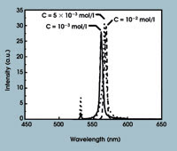
Figure 6. The three laser peaks (561, 567 and 569 nm) resulted from different dye concentrations in the microfluidic loop. Reprinted with permission of Applied Physics Letters.
“The tunability of the laser is limited, but we are working to improve it,” said investigator Jean-Christophe Galas.