Dick Rieley, Ophir-Spiricon LLC
Laser beam power, spot size and focal point must be measured and controlled to produce parts to specification through 3-D printing.
Laser-based additive manufacturing (AM) involves the deposition of a precise amount of material in a layer-
by-layer process to produce components of specific measurements and physical properties. Instead of milling a workpiece from a solid block, AM builds up components layer by layer using materials that are available in a powder form. A wide variety of materials from plastics to metals and even composite materials can be used.
The process is dependent upon the precise delivery of the laser heat source to produce the deposition, usually by melting a powder feedstock in a predictable thickness, layer upon layer, in a fully fused manner. Although the term “3-D printing” is on the rise, AM is a more accurate description, because it captures the method’s distinct difference from conventional approaches to materials removal.
Several variables impact the quality of an additive manufacturing process. The laser source is critical, especially in terms of its power, spot size and focal point. If any of these three variables is not properly measured and controlled, the likelihood of producing a part to specification is improbable.
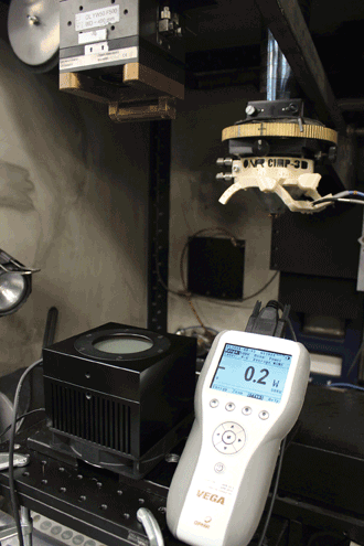
Figure 1. This experimental setup to measure laser beam power includes an optical head with copper collar, a 500-W fan-cooled sensor and the Ophir Vega digital display meter.
In a recent application with the Center for Innovative Materials Processing through Direct Digital Deposition (CIMP-3D) at Pennsylvania State University in State College, Pa., a complete beam-diagnostics procedure was conducted on one of the lasers used for additive manufacturing research. The system evaluated was a 500-W fiber laser from IPG Photonics with a 50-µm core fiber. It was fitted with a custom lens assembly that could deliver an estimated 50-µm focal spot to the point of processing, enabling very fine features to be fabricated during deposition.
The first part of the test involved verifying that the selected power level entered by the operator and controlled by the laser power supply was indeed delivered to the work surface. If the amount of power requested is not what is delivered, the process may not perform as desired, and there is a potential for a lack of fusion of the AM powder materials, which could lead to defects in the component under construction.
Setup: Power measurement
To conduct this test, the laser optical head was positioned so that the beam diameter on the Ophir 500-W fan-cooled thermal sensor would remain below the damage threshold of the absorber disk. With a beam spot size of 5 mm, the power density (irradiance) of the beam was estimated to be 2546 W/cm2, which corresponds to 33 percent of the damage threshold of the sensor, a very safe level.
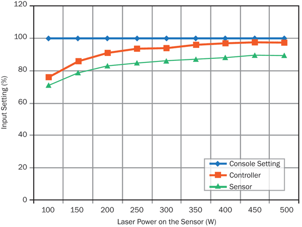
Figure 2. Plot of laser beam measurement results. The actual power delivered to the part is lower than the set point, but
the discrepancy is a significantly larger percentage of full scale at low power compared with higher-power settings.
A series of tests was conducted involving increasing laser power in 100-W increments – 100, 200 and up to 500 W.
At each step, the operator recorded the input power, measured the corresponding power setting on the laser controller, and took a final measurement of the actual power output on the 500-W sensor at the work surface of the laser.
Figure 1 shows the experimental setup. The optical head is visible with the copper collar, the 500-W fan-cooled sensor is located directly below the optical sensor, and the Ophir Vega digital display meter (used as a readout device for each measurement) is directly to the right of the sensor. In a production environment, the Ophir Juno would be used in place of the Vega meter, because the Juno allows the sensor to be connected directly to the PC, providing a live feed of the data to the monitoring controller or PC.
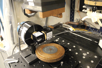
Figure 3. Photograph of the setup used to characterize the focused laser beam.
Results: Beam power
Figure 2 shows a plot of the results. The first measurement showed that, as expected, the actual power delivered to the part is lower than the set point. However, it is interesting to note that the discrepancy is a significantly larger percentage of full scale at low power compared with higher power settings. In the chart, the blue line represents the set point at each level at which the laser should be performing, the red line is the display output on the laser controller, and the green line is the actual delivered power to the 500-W sensor at the work surface.
The initial summary of this data is that when the laser is operated at a lower power setting, a discrepancy of as much as 29 percent can exist between the set value and the actual delivered power. In comparison, when the laser setting calls for a full 500 W, the actual delivered power is only 11 percent less. This test provides a performance baseline for this laser. When subsequent power tests are conducted, the results can easily determine stability or change from this baseline. If there is a change, the appropriate diagnosis should be made and corrective action taken.
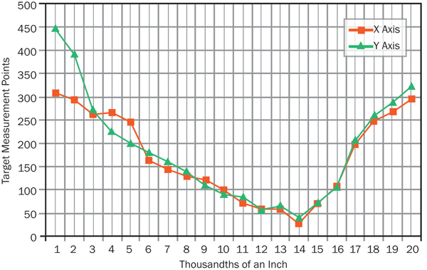
Figure 4. Beam-diameter measurements in both the X and Y dimensions, taken from each of the
prescribed increments.
This information also affords the operator the opportunity to determine within the laser what is causing the discrepancy between input setting and output results. With each corrective action, a follow power can then be conducted to validate the action as correct or ineffectual.
Beam size, location
The second part of the experiment involves measuring the beam size and focal-point position. To accomplish this, the Ophir Photon NanoScan rotating slit detector was used with a 9 mm × 5 µm slit. In this setup, the optical head of the laser was positioned to deliver the estimated 50-µm beam directly onto the scanning slit of the detector for measurement.
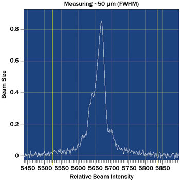
Figure 5. Beam profile near the focal point (in the X direction). FWHM = full width half maximum.
The detector first must be set up to handle the power density of a 50-µm laser beam delivering 500 W of power; the calculated density is 25.46 MW/cm2. To allow such a high power density onto the slit without causing damage to the measurement device, a dual front-surface beamsplitter was attached to the face of the detector so that, combined with optical wedges, it offers a maximum measurable power density of 100 kW/cm2.
Figure 3 shows the experimental setup used to make these measurements. The NanoScan has a dual prism just beneath the optical head of the laser. Beneath the first prism is a 5/8-in.-thick copper plate that was used as a beam dump to absorb the 460 W of laser beam power from the first prism.
In this setup, the first wedge split was 90 percent or 460 W of the maximum delivered power. The second wedge split was 90 percent of the remainder, or 36 W, where a simple 40-W power meter beam dump was used (not shown).
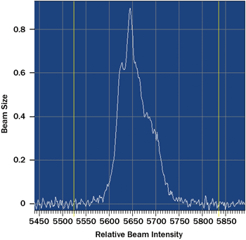
Figure 6. Beam profile near the focal point (in the Y direction).
Figure 4 shows the size of the beam in both the X and Y dimensions taken from each of the prescribed increments. The initial findings showed that the beam was slightly smaller at the focal point than was calculated. In addition, the location of the focal point was slightly below the estimated focal point. It was also determined that the “calculated” location of the focal spot was not exactly where it was expected to be – another key element in the performance of the laser contributing to a quality product. Further testing is needed to verify this information, but the results point to the need for further diagnosis of the laser settings and operation before preparation of production parts.
The measurement procedure consisted of taking 25 separate readings, starting at 0.375 in. above the estimated focal point (identified as zero-zero) and proceeding at increments of 0.03126 in. down to 0.375 in. below the estimated focal point. The chart in Figure 4 shows the plot of the beam size, and Figures 5 and 6 show cross-section measurements of laser beam power near the focal point.
These tests showed that, with this setup, the laser beam power lost between the set point and the substrate was quantified, the laser beam spatial energy distribution was quantified, and the predetermined location of the focal spot was quantified.
With this information, it is possible to define an AM procedure that specifies the power level, spatial energy distribution of the laser beam delivered to the substrate, and the focal spot, ensuring repeatable results.
Meet the author
Dick Rieley is the sales manager for the mid-Atlantic region at Ophir-Spiricon LLC; email: [email protected].
For additional information about additive-manufacturing research at Penn State University, contact Dr. Richard Martukanitz, the head of the Laser Processing division and director of the Center for Innovative Materials Processing through Direct Digital Deposition at the Applied Research Laboratory. Email: [email protected]; phone: (814) 863-7282.