Trey Turner, Matt LaChapelle and Roger Kirschner, REO Inc.
An optimized active optical alignment process enables accurate, cost-effective production of precision lens assemblies.
An optomechanical engineer faces many challenges when assigning tolerances for precision lens assemblies. Beginning with a functional requirement for optical centration, the engineer must determine mechanical tolerances for the various lens and housing components that ensure compliance cost-effectively. To avoid overspecifying such tolerances, it is helpful to understand alignment and assembly processes that can achieve different levels of accuracy in the resulting optical centration. The lens assembly’s centration level should direct the optomechanical engineer to the most appropriate assembly technique.
Active optical assembly techniques attain levels of centration not possible with mechanical alignment methods. Lens centering can also be less expensive using active optical alignment procedures.
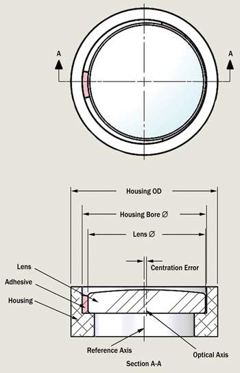
Figure 1. Mechanical alignment.
As an example, we will evaluate a simple 1-in.-diameter planoconvex lens. The standard mechanical method of lens alignment, which uses shims to center the lens, will be compared with active optical alignment, which uses the lens’s optical returns for centration. For lower centration requirements, the mechanical method is most economical. However, there is a crossover where the active optical alignment method actually becomes less expensive. Tighter centration drives up mechanical component costs, and eventually the mechanical alignment technique is no longer feasible.
Mechanical alignment
The most common and simplest way to mount a lens is what we will call the mechanical alignment method. A lens cell and the lens itself are produced with relatively tight diameter tolerances. The gap between the housing cell wall and the outer diameter of the lens is designed for a minimal separation. The lens is then normally centered within the housing, with three equal-thickness shims inserted between the cell wall and the lens. Adhesive is applied, and once the adhesive sets up, the shims are normally removed from the assembly.
Alternatively, the lens can be held in place with hardware such as retaining rings. The mechanical alignment method relies on the inherent tolerances of the optic and the mechanics, including the shims and the centration process, to accomplish this assembly technique.
When trying to achieve a tightly toleranced assembly, this method will normally use mechanics and optics that are more difficult or expensive to manufacture. The tighter the required centration, the tighter the fabrication tolerances must be for the cell bore, the lens-mounting surface, and the centration and outer diameter of the lens. This can make insertion of the lens into the cell and the placement of the shims difficult. For multielement assemblies with multiple lenses of the same diameter, both inserting the lens down into the barrel of the cell and placing the shims around the lens become nontrivial issues. Under some circumstances, the lens can bind on the cell walls and not bottom out onto the lens-mounting surface.
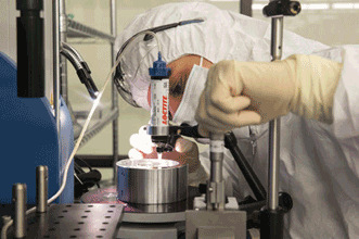
Figure 2. An assembly technician performs the final bonding of an active optically aligned assembly.
Additional steps may also be needed: for example, spot curing the lens in place with a UV-curable adhesive and then performing the final bond with either RTV room-temperature vulcanizing or a thermal-cure adhesive.
To achieve accurate centration of the optical axis relative to the housing outer diameter, the standard mechanical method relies on the alignment of the two lens surfaces to the optical axis, the optical axis to the outer diameter of the lens, the mechanical housing’s inner-diameter tolerance and the outer diameter to the inner diameter’s centration. The assembly technician’s ability to successfully maneuver the lens down the barrel to the lens-mounting surface, to center the lens, and to accurately bond while maintaining alignment can also influence the cost and performance of the assembly.
Optical alignment
The optical method of alignment leverages how the lens actually performs relative to the mechanical mount of the lens cell, which is what the engineer needs from the lens assembly. An alignment process that compensates for errors introduced by component fabrication is very useful. This alignment method is called “active” because the assembly technician or engineer actually uses the optical return from the lens to set it into the final position.
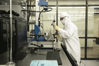
Figure 3. A technician sets up active optical alignment with commercially available equipment.
The mechanical mounting surface of the lens assembly is coaligned to the rotating axis of a precision air-bearing spindle. The process involves either mechanically minimizing the runout variation between the spindle axis and the lens-mounting surface, or looking at the optical return from an alignment fixture. The lens is inserted into the lens cell, and the position is moved into place actively by monitoring either the lens surface’s reflected return or the transmitted return. In reflection, the center of curvature from the lens surface is used. An autocollimator is used to provide the optical return. In transmission, it is the lens’s focal point. It is even possible to obtain increased accuracy by incorporating a Fizeau interferometer and monitoring the fringe pattern.
By adjusting the position of the lens on its mounting surface, the optical axis can be fine-tuned relative to the cell’s mechanical axis. Unlike the mechanical alignment method, the active optical method has less need for certain component attributes to be held to very tight tolerances.

Figure 4. An REO custom setup is shown with the software used to perform an active optical assembly alignment.
The centration of the lens’s optical axis relative to its outer diameter can be less constrained. Both surfaces still need to be fabricated relative to each other to define the optical axis; however, the centration requirement relative to the lens’s outer diameter and the optical axis is minimized. The lens cell’s mechanical mounting surfaces relative to mechanical bore can also be relaxed. This contributes to lower-cost components. When this technique is applied with multiple lens elements, the cost savings add up rapidly. Finally, the gap between the lens’s outer diameter and the cell bore can be larger compared with the tight gap of the mechanical method. This makes the installation of the lens in the bore significantly easier, without the need to insert shims in a very narrow gap.
Neither the active optical nor the mechanical alignment methods can completely correct for the misalignment of the optical element’s two surfaces relative to the optical axis. For the mechanical method, the image displacement caused by the optical surface misalignment is fixed and cannot be minimized. However, using the active optical technique enables a “composite” alignment that can sometimes be set, offsetting some of the inherent individual surfaces’ misalignment errors.
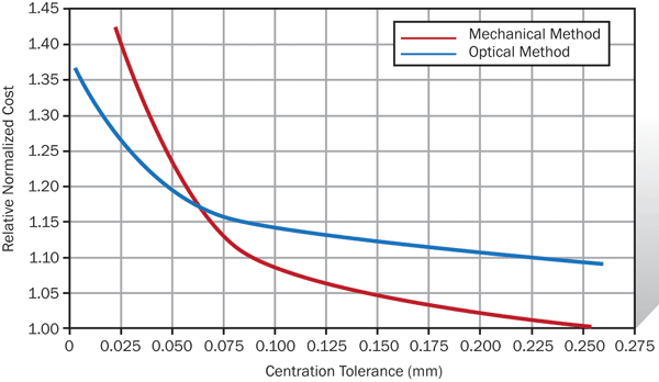
Figure 5. Lens element centration error in millimeters vs. normalized costs: A comparison of active optical alignment (blue) to mechanical alignment (red) for a simple planoconvex lens assembly.
Cost comparison
To compare these two assembly methods, we applied a cost calculator used for the production of optics and assemblies at REO. For this evaluation, we selected a simple planoconvex, 1-in.-diameter BK-7 lens with a 2-in. focal length, 1/10-wave irregularity and a 10-5 surface quality. The lens mount was kept to very simple lens housing. The two assembly methods were evaluated for a broad range of tolerances, from a relatively loose 0.26-mm centration to a quite stringent 0.0025-mm centration.
The four major cost contributors are the optics, the mechanical housing, the assembly and the metrology. These were combined for the range of assembly centration tolerances. Figure 5 illustrates the combined costs over the centration tolerance range for the mechanical alignment method (red line) and the active optical alignment method (blue line).
As expected, for looser centration tolerances, with centration above 0.1 mm, the mechanical method is less expensive. However, for tighter tolerances, below 0.075-mm centration, the cost discrepancy between the two methods disappears, and the active optical alignment method is actually less expensive than the mechanical method. In fact, beyond a certain level of centration tolerance (0.025 mm), it is actually impossible to produce an assembly using the mechanical methods.
Figure 5 provides the two assembly methods’ normalized costs for the simple lens assembly as a function of the centration tolerance. The centration tolerance from 0.275 mm to below 0.025 mm is on the X axis, and the Y axis shows the normalized costs. The crossover point where the red and blue lines intersect is where the two assembly methods’ costs are equal. To the left of this crossover, the assembly is less expensive to produce with active optical alignment. To the right, the mechanical assembly method is more economical.
For centration tolerances to the right of the crossover point, the component tolerances are loose enough to be significantly lower than the additional cost of active optical alignment. For an assembly requiring tighter than 0.075 mm, the component costs of the mechanically aligned system overwhelm the additional cost of optical alignment, and the optically aligned system becomes more affordable.
Similar analysis for multiple-element lens assemblies indicates that this crossover of alignment method costs is actually magnified. The increased difficulty and cost of maintaining multiple surfaces for multiple setups lead to increased mechanical alignment costs, increased mechanics costs and increased optical component costs.
A number of factors contribute to the overall expense of a lens assembly, including the lens component cost, the mechanical housing cost, the metrology cost and the assembly cost. When tighter centration tolerances are necessary, then active alignment with a view to overall assembly costs is the key to a cost-effective solution.
Meet the authors
Trey Turner is the chief technology officer at REO Inc. in Boulder, Colo.; email: [email protected]. Matt Lachapelle is an assembly process engineer; email: [email protected]. Roger Kirschner is the business development manager; email: [email protected].