From reverse projection to modulation transfer function testing, there is more than one way to evaluate the resolution of a lens.
Patrick McKenna, edmund optics inc.
In the days of VGA video cameras and predominantly analog storage, it was easy to make an imaging lens that would outperform the camera’s ability to capture an image. That’s no longer the case. Where 640 pixels once stood,
it is not uncommon today to see 6 million. Cameras
continue to offer smaller pixels (and more of them), and all machine vision users — from the largest integrators to the lone person in the lab — want to get the most out of this
plethora of pixels. Lens manufacturers have had to up
their offerings, pushing the limits of optics, mechanics,
and design to keep pace.
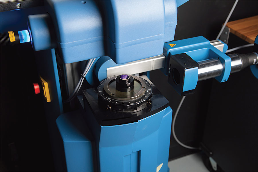
A commercially available modulation transfer function (MTF) test station from Trioptics tests an imaging lens. Courtesy of Edmund Optics Inc.
As increasingly demanding requirements are placed on
the lens, evaluating its performance becomes both more
important and more challenging. There is no single “right” way to test a lens; the same lens may require multiple test methods when employed in multiple applications. Testing comes with trade-offs. It’s not as simple as making concessions on accuracy to gain speed. To weigh these trade-offs,
what follows are assessments of the most common testing
methodologies for resolution and enough context and
real-world application comparisons to illustrate how machine
vision lenses are evaluated.
The discussion is limited to methods for evaluating resolution because, while there are many performance parameters that are of interest to machine vision users, the most important is resolution. It is the parameter that is pushed the hardest by the ever-decreasing size of pixels. It’s also the
parameter with the deepest well of literature on testing.
Resolution is generally the first thing one notices about the
performance of a lens. And, luckily, when testing resolution,
there is often information to be garnered about other
performance parameters, such as distortion and relative
illumination.
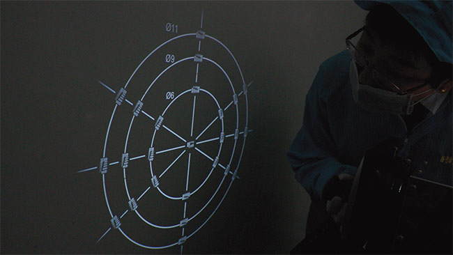
An operator performs a test using reverse projection. The circles labeled 11, 9, and 6 correspond to the image circles of 2/3-in., 1/1.8-in., and 1/3-in. sensors, respectively. Courtesy of Edmund Optics Inc.
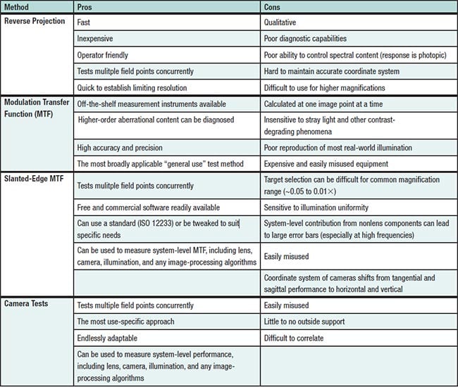
The most common of these methods for evaluating the resolution of a lens are: reverse projection, modulation
transfer function (MTF) testing, slanted-edge MTF testing, and camera testing. Each offers pros and cons (see table),
with considerations for real-world analog and the type of
information gathered.
The performance of all lenses differs at every point within
an image — a 2D space — and at every conjugate: the third dimension. When one considers this 3D performance function, it is important to remember that the function is continuous, and therefore sampling within the space need only
be fine enough to set reasonable boundaries of expectation.
For instance, if you test the condition of a lens at a working
distance of 1 m, and you want to know what the performance will be at 1.01 m, it probably won’t change much.
Reverse projection
Reverse projection, as the name implies, is the use of the lens under test as a projector, thus reversing the typical imaging use. It requires that a very high-accuracy target be used as the “film” part of the projector. This works for two reasons: First, the performance of a lens is reversible, so going from image to object space is the same as going from object to image space. Second, resolution performance is generally given in image space where the pattern is located.
Comparison of Common Methods for Evaluating the Resolution of a Lens
The pattern consists of several orthogonally oriented bar targets (such as USAF 1951), where sets of bar targets of varying frequencies are arranged in radial rings that match common sensor formats. This allows for concurrent testing of multiple field points. The operator can evaluate the lens with a focus that balances all of the field points or maximizes zonal performance. This is ultimately a 2D evaluation of
the 3D performance function referenced above.
Reverse projection is favored for its speed and low
material cost. Operators can be relatively easily trained,
and equipment, although not particularly standardized, has
a lower cost compared to most methods. The position
and condition of the target are paramount to the efficacy
of this test and, if properly designed, it can allow a highly
trained operator to perform limited diagnostics.
Reverse projection is directly comparable to barcode and scanning applications because of the use of bar-style targets. Since the “detector” in this situation is the eye of an operator, the response is intrinsically photopic. And while operators can be trained to recognize a specific contrast limit (usually 20 percent), they cannot be trained to recognize arbitrary contrast levels, which means the data generally takes the form of the lowest resolvable contrast at each target portion field point. Comparison of the orthogonally oriented bars can give a measure of astigmatism.
Modulation transfer function
It would be fair to consider modulation transfer function (MTF) the gold standard of lens performance. It allows for apples-to-apples comparison of the imaging capabilities of lenses across multiple use cases and can be very precisely calculated. Commercially available test benches allow for programmatically addressable testing within an arbitrary coordinate system. This is achieved by passing
an impulse through the lens under test while carefully controlling the positioning of the object and image. The impulse response allows for calculation of the response at any frequency up to Nyquist (the highest resolvable sampled frequency), and the arbitrary coordinate system allows for sampling within the 3D-performance function to whatever level of finesse is necessary for the application.
MTF measurements are most comparable to astrological imaging and certain microscopic techniques — such as fluorescence microscopy — where small, bright objects are imaged against a dark background. The highly controlled
test environment sometimes desensitizes the measurement to real-world phenomena such as stray light. In other
words, imaging bright objects against a less bright background leads to the observation of falloff in the measured performance of MTF, so MTF can also be thought of as
the upper limit of performance.
The calculations from an MTF test bench are, by definition, contrast as a function of spatial frequency within a
1D-, 2D-, or 3D-coordinate system. “Contrast as a function
of spatial frequency” is another way of saying how well-resolved an object is, based on its size, and this is the
most common metric of resolution.
Careful examination of MTF data can be highly diagnostic.
Comparison of performance can lend itself to quantification of lateral color, field curvature, astigmatism, and other
higher-order aberrations. Additional calculations based on centroid locations and energy on detector can lend
additional performance metrics, such as distortion and
relative illumination, among others.
Slanted-edge MTF
Slanted-edge MTF measurements are a quicker, more adaptable version of MTF. Rather than using expensive,
proprietary equipment, the same contrast as a function of spatial frequency information is calculated using a camera
and the lens under test by looking at a high-contrast edge target. This has the advantage of being able to calculate
system-level MTF by incorporating the contribution of the lens, as well as the camera, the illumination, any imaging
processing algorithm, and even the cables. Alternatively,
the contribution of the lens can be calculated with a high
degree of accuracy by dividing out the contribution of
everything else (since MTF is multiplicative).
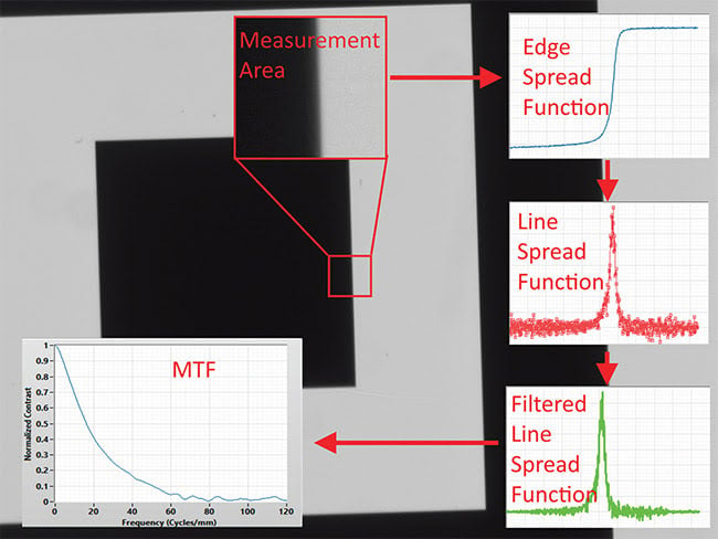
A slanted-edge MTF measurement. Multiple measurement areas can be concurrently tested. Courtesy of Edmund Optics Inc.
As in reverse projection, a lot depends on the edge target. The first step in calculating slanted-edge MTF is measuring the edge spread function. The derivative of the edge spread function is the line spread function, which is then filtered and used to calculate the MTF. This only works if the edge target is a near-perfect transition in the image, with “near-perfect” meaning at least 4× smaller than Nyquist. The real-world implication is that, if the edge target has an edge transition
of 100 µm — which is typical for a home printer — and the aim is to measure resolution up to 100 lp/mm (5-µm Nyquist sample size), one could only use that edge target if magnification is less than 0.0125×. (See equation.)
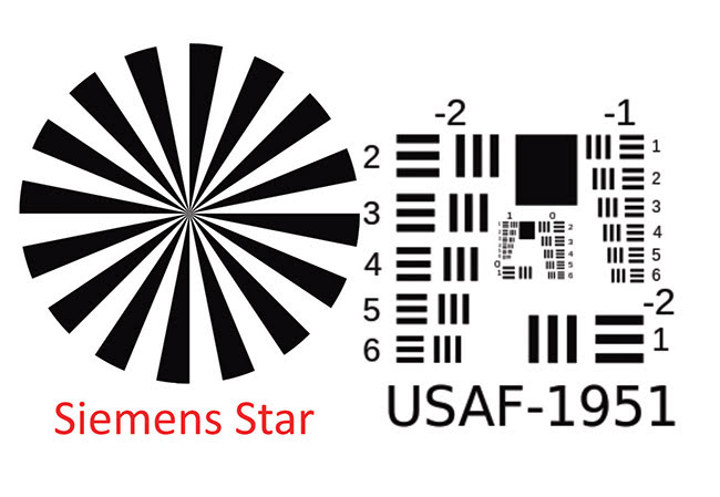
Common resolution targets for camera testing. Courtesy of Edmund Optics Inc.
equation
Image space edge transition width < Nyquist ÷ 4
Object space edge transition width × magnification < Nyquist ÷ 4
100 µm × magnification < 5 µm ÷ 4
Magnification < 5 ÷ 400
Magnification < 0.0125
Of course, there are higher-quality printers and other
ways to obtain a better edge transition on a target, but this illustrates the importance of picking the right edge target.
For high magnification, very high-quality lithographic and
photomasked edge targets are readily available. As shown
in the equation, very low magnification allows for the use of printed edge targets. For in-between magnifications, it is
often difficult to find a target that is both accurate enough
and large enough to allow for measurements at all points
of interest in the field simultaneously.
Camera tests
“Camera test” is a catch-all term for any test performed using a camera, such as magnification, distortion, or any use-specific test. Many deployed systems incorporate
some form of camera test as a calibration routine. Slanted-edge MTF is a specific instance of a camera test, but is
far from the only common camera test for resolution.
Another common target is the Siemens star, where the shape and size of the resolvable area are used to calculate
resolution. There is also the USAF 1951 target, which presents orthogonal bars at discrete frequencies.
There is no single ‘right’ way to test a lens; the same lens may require multiple test methods when employed in multiple applications.
Camera tests can be made analogous to any real-world process, and it is very common to have use-specific targets constructed to allow for the most accurate, use-specific measurement of resolution. Camera tests can be set up to allow not just for measurements at multiple field points but for measurements of multiple parameters at multiple field points. Checking the spacing between bars on a USAF target, for instance, can check magnification. The applications are only limited by the tester’s ability to implement.
As sensors continue to move to smaller and smaller
pixels, they will further push the limits of optics, mechanics,
and design. System integrators and machine vision end users often don’t realize that optics can be the limiting part
of their system, not the size of the pixels on their sensor.
Understanding the advantages and disadvantages of
different types of test methodologies used for evaluating lenses can help customers understand exactly what level of performance they can expect from their imaging lenses.
Meet the author
Patrick McKenna is a senior optical test engineer at Edmund
Optics Inc. He is a system-level metrology and testing
specialist with more than 10 years of experience in custom test bench development and quantification of optical
performance criteria; email: [email protected].