CINDY GOPPOLD, THOMAS PINDER AND PATRICK HERWIG, FRAUNHOFER IWS
Even though thick plate cutting has a subsidiary market share in laser material processing, it is still a necessary feature for state-of-the-art machines. In recent years, research has concentrated on various quality issues, especially dross attachment and surface appearance, that compromise productivity. This has resulted in notable improvements.
About $1.1 billion was allotted to research and development of macro laser metal cutting in 20161. Roughly 20 percent of this research addressed sheet thicknesses above 4 mm. Ongoing market monitoring points to a persistent industrial interest in this sector, because thick plate performance is a benchmark of laser cutting machines. CO2 laser cutting remains the established method for industry; every laser cut is compared with CO2 quality.

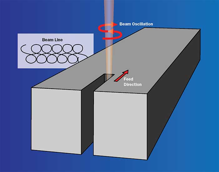
Figure 1. Dynamic beam shaping (DBS) superimposes two movements of the laser beam: the movement of the cutting machine and a high-frequency oscillation of the laser beam inside the cut kerf. To see an animated version of this drawing, go to https://youtu.be/cUm231Ya6is. Courtesy of Fraunhofer Institute for Material and Beam Technology IWS.
However, in recent years the market share of solid-state laser cutting devices has increased by a compounded annual growth rate of more than 10 percent2. Solid-state lasers offer various advantages, such as higher efficiency, easier handling and faster feed rate for thin sheets. However, in the case of thick plates, they have not achieved acceptable cut quality, nor even a higher feed rate in comparison to CO2 cutting.
A basic approach to achieve optimal results for solid-state laser cutting is to adjust the cut kerf dimensions for each application. (Of course, these must take into account influencing factors such as energy deposition and heat conduction.) In the case of thick plates, an appropriate kerf width is required to maintain melt ejection.
Static beam shaping is one common method for adjusting cut kerf dimensions, but the result is not always sufficient. With this technique, various optical elements can be utilized to modify the laser beam for spot size, beam geometry, amount of foci, polarization state and other factors. The result is an optical setup that suits a specific cutting task. This is advantageous for specialized tasks such as serial production. But static beam shaping cannot adequately accomplish the frequently varying operations that constitute the daily business of industry.
In addition, with solid-state laser cutting of thick plates, mechanical post-treatment typically is needed to remove dross. Thus, an additional production step is necessary that requires manpower and machinery. Static beam shaping can overcome this challenge by using laser sources with higher output power. Although this increases productivity, it also increases investment and running charges.
Innovative laser cutting
Fraunhofer IWS is pursuing dynamic beam shaping (DBS) as a solution to the challenge of laser beam cutting of thick metal plates. It addresses high productivity, improved quality and efficiency in combination with standard equipment. The technology is considered an add-on to the conventional process.
The concept is based on two superimposed movements of the laser beam (Figure 1). The first is the movement of the cutting machine, defined by the feed rate and the part geometry. The second is an additional, high-frequency oscillation of the laser beam inside the cut kerf. As a consequence, energy deposition is distributed more homogeneously within the material, resulting in an optimized cut kerf.

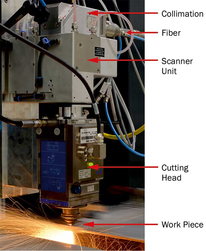
Figure 2. Implementation of DBS requires a high-dynamic 2D-scanner unit in addition to standard components. The scanner is installed between collimation and the cutting head. Courtesy of Fraunhofer Institute for Material and Beam Technology IWS.
In contrast to static beam shaping, DBS is a spatiotemporal method during the cutting process and is variable at any time. Implementation requires a high-dynamic 2D-scanner unit in addition to standard components. The scanner consists of two oscillating mirrors to achieve a defined deflection of the laser beam in the focal plane. All hardware for DBS is off the shelf and ready for integration into cutting machines. Optical properties are not affected by the setup, since the scanner is installed between collimation and the cutting head (Figure 2). Fraunhofer IWS is currently working on further optimization of hardware components in order to decrease the integration space and develop a smaller drive mechanism.
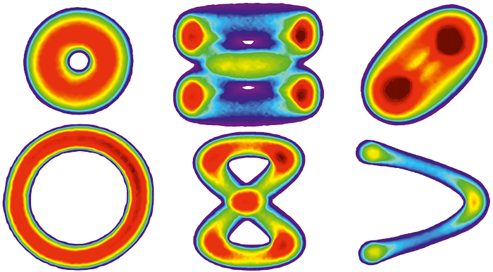
Such a scanner supplies an additional five adjustments to the laser beam cutting process. Each mirror has a time-dependent position, defined by a certain frequency and amplitude. The phase shift between both mirrors provides the fifth parameter for controlling the cut kerf generation. As a result, an infinite amount of arbitrary beam movements is possible (Figure 3). In addition, depending on the chosen parameters, oscillation speeds of the laser beam in the cut kerf can go as high as 500 m/min.

Figure 3. As this diagnostic of DBS patterns shows, an infinite amount of arbitrary beam movements is possible. Courtesy of Fraunhofer Institute for Material and Beam Technology IWS.
The artificial laser beam geometry created by DBS is easily adjustable by a software tool to accommodate many different cutting tasks. Nevertheless, tuning of the oscillation parameters according to each task is still the secret of success. Expert attention has to be paid to peripheral conditions such as the material, sheet thickness, optical setup and laser source.
Improved cuts
One routine related to static beam shaping is adapting the optical setup to varying tasks. Thin sheet cutting usually requires small focus spots, whereas thick plates are preferably separated by focus spots around 200 μm. The change requires mechanical replacement of the optics. With DBS augmented laser beam cutting, a shift to thick plate cutting can take place without mechanical adaptions and therefore without any operator interaction. The proper beam characteristic for a certain cutting task becomes a smart parameter, stored in a database and controlled by the programmable logic controller. Just one universal optical setup is required. In addition to trimming one production step, this eliminates the need to keep multiple optics in stock and reduces the possibility of error during the adaptation process.
Besides providing a user-friendly system, DBS also improves feed rate and cut edge quality. Increasing the achievable feed rate allows more parts to be manufactured and reduces costs per cutting meter. A higher feed rate also flattens the cut front angle. This enlarges the interaction area of laser beam and material surface, reduces transmitted power loss, and enhances process efficiency.
This greater efficiency means that almost every solid-state laser can use DBS for thick plate cutting. In case of laser beam fusion cutting of stainless and mild steel above 8-mm sheet thickness, a productivity increase up to 200 percent is possible without any accompanying increase in power. The cut quality of DBS also is improved compared with static beam shaping at the same power level. Process stability is similar to established industry standards. In combination with common sensor systems and refined signal evaluation, even a smart process is possible.
With stainless steel, DBS reduces post-treatments to a minimum because the dross attachment is significantly decreased and the generated kerf is almost parallel.

Figure 4. Cut edges created by DBS at 3-kW laser power of the two main materials in metal processing: mild (left) and stainless steel (right). With stainless steel, DBS reduces post-treatments to a minimum, while mild steel plates are dross-free and nonoxidized. Courtesy of Fraunhofer Institute for Material and Beam Technology IWS.
So far it has not been possible to cut mild steel plates above 8-mm sheet thickness by a laser fusion cutting process with acceptable quality. DBS, however, can yield dross-free, nonoxidized edges. The results of laser beam fusion cutting for both stainless and mild steel are achieved with 3 kW and are of comparable quality to results achieved with higher laser power and static beam shaping (Figure 4). The reduction of subsequent post-processes enabled by DBS also means a reduction of work time and necessary machinery compared to other processes.
DBS also provides more applications for laser beam ablation such as piercing and drilling and makes it possible to work with materials such as aluminum that traditionally have been difficult to separate with lasers.
Meet the authors
Cindy Goppold is research associate in the department of laser ablation and cutting at the Fraunhofer Institute for Material and Beam Technology IWS in Dresden, Germany; e-mail: [email protected].
Thomas Pinder is a research associate in the department of laser ablation and cutting at Fraunhofer IWS; e-mail: [email protected].
Patrick Herwig leads the laser cutting group at Fraunhofer IWS, focusing on efficiency and quality improvements for conventional laser cutting processes and the development of new technologies; e-mail: [email protected].
References
1. D. Belforte (2017). Industrial lasers continue solid revenue growth in 2016. Industrial Laser Solutions, Vol. 32, Issue 1.
2. P. Hilton and A. Gillner (2016). Portfolio and trend analysis for laser based manufacturing EU-funded projects and markets. EU-Report BU33 04/77 B-1049.