To maximize the performance of a coating for a given application, a better understanding of coating design and deposition technique is a must.
STEFAAN VANDENDRIESSCHE, EDMUND OPTICS INC.
Optical coating design and performance are critical for a growing number of applications in fields as diverse as biomedicine and astronomy. Coatings can perform a variety of functions, from imparting high reflectivity on telescope mirrors, to controlling polarization and removing unwanted reflections. As laser usage continues to increase globally, the use of laser-specific optical coatings increases in tandem. The ongoing improvements in laser power, pulse length and wavelengths have resulted in new coating requirements, spurring the development of novel coating technologies.

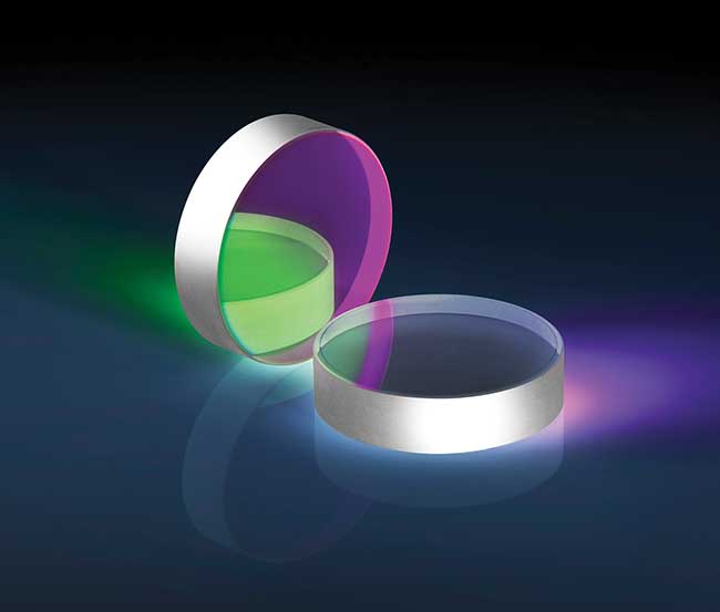
TECHSPEC Nd:YAG Laser Line Mirrors offer the high reflectance and superior surface quality and accuracy needed for demanding laser applications.
The interactions of high-power lasers and optical coatings are complex and depend on the laser’s wavelength, pulse length and intensity. On the other side, coating performance is impacted by the uncoated substrate, coating design and deposition technique.
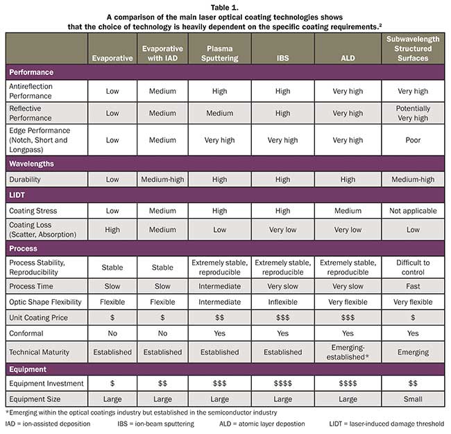
There are many methods for manufacturing optical coatings; therefore, a solid understanding of the benefits and disadvantages of each technique, along with the interplay of the laser with the design of the coating and the uncoated substrate, helps in the selection of the proper substrate, coating technology and requirements for the given application. Achieving the required performance without over-specifying the optic or choosing an unnecessarily expensive substrate or coating technique can save on cost and provide engineering benefits that directly impact the bottom line (Table 1).

Specifying a substrate
Often the first material that comes to mind for laser optical applications is fused silica, favored for its low coefficient of thermal expansion. For that reason, it is often the best choice for an application, yet it typically comes at a price premium compared with other materials.
The common misconception is that fused silica is the only choice due to its high laser-induced damage threshold (LIDT). This is a pitfall to avoid when specifying laser optical substrates, as many other common materials exhibit similar bulk material LIDT as fused silica in the correct material purity grade1. Generally the bulk material LIDT is irrelevant as the coating or coating-substrate interface will fail at laser fluences many times lower than that of the bulk material.
Another commonly misunderstood requirement for optical coatings is surface roughness. While it’s important for laser optical performance, including scatter and laser damage threshold, specifying roughness correctly without unnecessary over-specifications and associated costs is often difficult. A useful surface roughness specification includes the maximum value of a measured metric, such as Ra or Rq, as well as the area over which the roughness is to be measured.

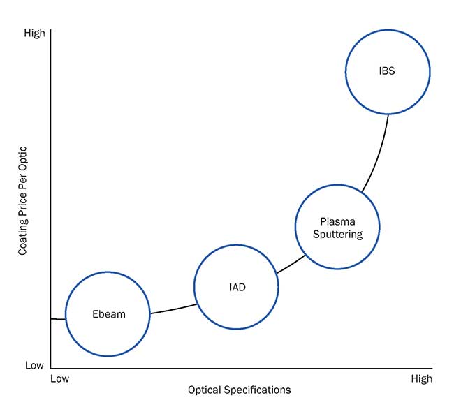
Choosing between the established coating techniques requires an understanding of the cost/performance ratios and trade-offs. This chart does not include emerging technologies, as their cost and performance metrics are not sufficiently determined for a general comparison with established technologies.
Subsurface damage is not often specified in substrate requirements despite the fact that it is an important factor in LIDT. The main reason to avoid specifying it is the difficulty in both controlling and measuring it. Often a process is developed that results in an acceptable laser optical performance and this process is carefully repeated to ensure the same subsurface damage without measuring or knowing what the actual subsurface damage is.
Specifying a coating
Typically a reflectivity is specified over a wavelength range, either close to 100 percent for mirror or reflective coatings or close to 0 percent for antireflective coatings. Specific reflection requirements are given for more specialized coatings such as notch, bandpass and edge filters, and these often include the slope: the degree that the reflectivity changes over a specific wavelength.
Environmental requirements include abrasion resistance and performance tolerances during humidity and heat changes. These are often important for laser applications in more demanding environments, such as laser steel welding.
Surface quality, similar to nonlaser optical coatings, is most often specified using either the MIL standard (MIL-PRF-13830B) or the ISO standard (ISO 10110-7:2008). When using lasers, slight surface imperfections generate highly detrimental scattering and are potential nucleation sites for laser damage, and for this reason laser optics are usually specified with 20-10 or less surface quality, and quite often 10-5 or lower.
LIDT is a seemingly simple specification that is very often misused and misunderstood. A properly defined LIDT
establishes a maximum irradiance (for continuous wave lasers, typically in kW or MW/cm2) or fluence (for pulsed lasers, typically in J/cm2) at a specific wavelength, pulse duration and repetition rate if applicable, laser beam spot size and beam profile. While it may seem straightforward, the existence of an entire ISO standard (ISO 21254-1:2011) of over 75 pages devoted to characterizing LIDT demonstrates that it is not as straightforward as it appears to be. Achieving a certain LIDT depends on the chosen coating technology3, the coating design4, coating materials chosen, process control and cleanliness during coating, as well as the substrate on which the coating is deposited. Moreover, the damage mechanisms depend on wavelength as well as pulse duration5. Damage either occurs within the bulk material, or at the surfaces and interfaces that include the thin-film coating.
Damage to bulk material and coatings
Damage to the bulk material most often occurs in uncoated laser optics. This is because the bulk material typically has a 3 to 10 times higher LIDT than the coating does. Bulk material failure can occur due to material impurities or inclusions, but this damage can be avoided by selecting the correct optical material for the required wavelength, and specifying the correct grade of optical material to avoid inclusions and impurities.
Damage most often occurs in the thin-film coating or at the surfaces and interfaces. Within the thin-film coating, it can be minimized with the correct coating materials and coating design. The electronic bandgap of the chosen materials influences the LIDT, and the purity of the coating materials is also an important factor. The design of the coating determines what the distribution of electric fields will be during irradiation, and an ideal design minimizes peak electric fields and places the highest electric field values as far from interfaces as possible.
Damage occurring at the coating-substrate interface can often be mitigated by correct substrate specification6. Often this damage is initiated by subsurface damage present in the substrate and could have been avoided by using substrates with less subsurface damage. This region is often the most important in determining LIDT.Damage occurring in this region is the reason transmissive coatings typically have significantly lower LIDT values than reflective coatings; most of the laser beam energy never reaches this relatively fragile region in reflective designs, whereas most of it does for transmissive coatings.
The exact mechanisms of laser-induced damage are the subject of countless articles and technical conferences and are beyond the scope of this article7. It’s important to understand how coating, substrate and process parameters influence LIDT in a given application, and this requires an in-depth discussion with your optical manufacturer.
Evaluating coating techniques
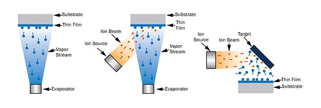
In evaporative deposition, source materials are vaporized using either resistive heating or electron-beam bombardment inside a vacuum chamber. These vaporized materials condense onto the optical surfaces and, through the careful control of vaporization rates, vacuum and substrate rotation, uniform optical coatings of specific designed thicknesses result.

Various coating technologies: electron-beam physical vapor deposition (a), ion-beam-assisted electron beam physical vapor deposition (b), ion-beam sputtering (c).
Because of the relatively gentle nature of vaporization, the resulting coatings are loosely packed or porous. These loose coatings suffer from water absorption, which changes the effective refractive index of the layers and result in a degradation of performance.
Evaporative coatings can be enhanced using ion-beam-assisted deposition, where an ion beam is directed at the substrate surface. This increases the energy of the source material when it adheres to the surface, resulting in stronger adhesion. The resulting coating is denser but also contains more stress.
Another coating technology is plasma sputtering, which covers a range of technologies encompassing advanced plasma sputtering to magnetron sputtering. All involve the generation of a plasma. The ions in this plasma are accelerated into the source material, striking loose energetic source ions. These then sputter onto the target optic. While each type of plasma sputtering has its own specific properties, advantages and disadvantages, these technologies are grouped together as they have a common operating concept and the differences among them are much smaller than the differences with the other coating technologies discussed here.
With ion-beam sputtering (IBS), a beam of ions is accelerated through a high-energy electric field. The beam then hits the source material with significant kinetic energy, “sputtering” the source material loose from the target. These sputtered source material ions are energetic and impinge on the substrate surface, creating a dense film. While IBS is well-established in the laser optical coating space, it is overused due to a lack in understanding the capabilities of the other coating technologies.
In atomic layer deposition, optical coatings are built layer by layer from gas precursors. Unlike evaporative deposition, the source material doesn’t need to be evaporated from a solid, but can originate directly from a gas. Despite this, the coating is often still performed at an elevated temperature. The key differentiator for atomic layer deposition (ALD) is that the precursors are delivered in non-overlapping pulses, and that each pulse is self-limiting. The chemical design of the precursors and the coated surface is such that only a single layer can adhere per pulse. This provides an extraordinary level of control for layer thicknesses and designs, but also results in a slow rate of deposition.
Clues from a moth’s eyes
Surfaces with structures smaller than the wavelength of light have been of interest ever since the discovery of the textured pattern on moths’ eyes. While this approach is still evolving, it consists of modifying the structure of a substrate’s surface as opposed to depositing alternating layers of high- and low-refractive index materials traditionally used in thin-film coatings. The features on the textured surfaces can be periodic such as the moth’s eye pattern, or random in nature. These structures can be manufactured using photolithography or using modified plasma etching.
Translating an application’s requirements to substrate and coating specifications is a crucial step in selecting the right coating technology. There is no single technology best suited for all applications; while some applications can be served by multiple coating technologies, generally it is possible to identify one most suitable method to deliver the necessary performance at the right price.
Meet the author
Stefaan Vandendriessche is a product line manager for laser optics at Edmund Optics in Barrington, N.J.; email: [email protected].
References
1. C.J. Stolz (Nov. 28, 2012). Boulder Damage Symposium annual thin-film laser damage competition. Opt Eng. Vol. 51, Issue 12, 121818.
2. R. Jedamzik and F. Elsmann (Feb. 22, 2013). Recent results on bulk laser damage threshold of optical glasses. Proc SPIE, Vol. 8603, High-Power Laser Materials Processing: Lasers, Beam Delivery, Diagnostics, and Applications II, 860305.
3. J. Shao and K. Yi, et al. (July 2011). Filters & coatings: Laser advances drive development of specialized optical coatings. Laser Focus World.
4. P. Kupinski and M. Thomas (September 2014). Transmissive high-energy laser optics: Manufacturing and testing considerations. Laser Focus World.
5. N. Bloembergen (1973). Roles of cracks, pores and absorbing inclusions on laser induced damage threshold at surfaces of transparent dielectrics. Applied Optics, Vol. 12, pp. 661-664.
6. A.A. Manenkov (January 2014). Fundamental mechanisms of laser induced damage in optical materials: Today’s state of understanding and problems. Optical Engineering, Vol. 53, Issue 1, 010901.
7. A. Czajkowski (2010). Optical coating technology and applications: Past and present to future. Photonik International.
Applications Determine Coating Choices
For high-reflectivity wavefront-critical mirrors used in cavity ring-down spectroscopy, the high reflectivity requirements narrow the coating technology selection down to plasma sputtering, ion-beam sputtering or atomic layer deposition, with the final choice often dictated by price, volume and batch sizes. The laser-induced damage threshold (LIDT) is not significant for this application, so the subsurface damage in the substrate is of lesser importance, too. To achieve the required reflectivity, the surface roughness will need to be very low. A super-polished fused silica substrate would be the recommended substrate and, due to the stress caused by the possible coating technologies, coating the nonreflective side may be required to balance out the stress.
In another case, a polarization critical lens for chemical analysis mandated that residual stress in the coating could distort the polarization and must be avoided at all costs. For this reason, the coating technology of choice is evaporative deposition. The fused silica must be specified to be low-birefringence fused silica, as standard fused silica would cause polarization distortion due to birefringence.
A third example involves high laser-induced damage threshold mirrors for a fiber optical laser machining application. Other than the LIDT, this mirror does not have very tight specifications that could be met with most coating technologies. Price becomes the most important remaining parameter, and the recommended coating technology is either evaporative deposition with ion-assisted deposition or plasma sputtering. The substrate can be any of the common optical materials, including N-BK7, fused silica and Zerodur, depending on the thermal specifications and material availability at the correct size and polishing price and time.