With the appropriate camera, imaging systems are capable of producing dramatically high-resolution images at fast speeds. However, choosing such a device may prove to be a challenge for both inexperienced and trained system users.
MYRIAM FRANCOEUR AND YOANN GOSSELIN, NÜVÜ CAMERAS
Knowledge of the most common sensor technologies and camera housing properties, along with their pros and cons in the context of low-light life sciences applications, will give users a better understanding of which camera parameters can increase a system’s output. With that information, the camera selection process can be illustrated through the design of a hyperspectral fluorescence-guided surgery device for brain tumor resection.
Life sciences strongly benefit from the analysis of light interacting with or emitted from biological materials, such as living cells under the microscope. They can provide invaluable information regarding composition, structure, inner dynamics and behaviors in a noninvasive manner. As a result, numerous imaging techniques based on such interactions have been developed — superresolution, single-molecule, FRET imaging and Raman spectroscopy are only a few examples. Promising diagnostic tools and treatments such as fluorescence-guided surgery are more recent examples of biological material-light interactions applicability and potential.
However, in many biomedical imaging applications, the desired signal is faint, whether emitted from a quantum dot marker, a fluorescent protein or Cerenkov process. This limits the capabilities of imaging systems since the signal-to-noise ratio (SNR) drops significantly in low-light imaging conditions. In other cases, the signal might be stronger, but speed requirements reduce the exposure time and thus the emission intensity on the detector per frame. Additionally, the signal may be attenuated by other light-based interactions such as absorption or diffusion that occur within the substrate or the system, or filtering by the organism. Light collection efficiency, or quantum efficiency, determined by the system’s optical component quality and its detector capabilities, further modulates the signal detection.
In some experiments, the markers or light source that make the object of interest visible under the microscope may alter the state of the samples. Such phenomena lead to chemical or light-induced toxicity that reduces the measurement time window due to the deterioration of the samples. Compromising between a light source or laser excitation intensity and sample longevity is necessary. In such conditions, detectors that can perform the acquisition of fainter signals, leading to lower source intensity requirement, allow imaging of biological samples for longer periods of time with the same image quality.
Today, a variety of sensor technologies is accessible to the user, encompassing a broad spectrum of applications, each with particular light detection requirements. Each detector is enclosed in a special package with cooling and driving systems — the camera — influencing detector capabilities and, thus, image quality. However, determining which camera will yield the best results may turn into a trial-and-error process, resulting in time and money loss. The answer lies in understanding which camera parameters can influence a system’s capabilities in the context of a particular application.
System optimization
If the right camera pushes imaging performances to the brink, fine-tuning a system boosts its efficiency as well. Indeed, in some cases, the system is not limited by its camera, but rather by its optics or optical background contamination, which is a common problem for live-cell imaging applications.
On one hand, system enhancements arise when choosing high-quality optical components, which maximizes light transmission, field of view, depth of field and contrast, while preventing image distortion. On the other hand, successfully eliminating light contamination from the background increases the likelihood of detection. Light leaks and intrinsic or nonspecific fluorescence may flood the signal of interest. The same goes for undesirable light sources such as secondary spectral emissions. Selecting the appropriate spectral range and filtering unwanted light improves the overall system capabilities for a given experiment.
Camera technologies
Conjointly with the system’s calibration, camera performance is determinative of an application’s effectiveness.
As has been mentioned, several sensor technologies are currently available to users. Considering that most life sciences applications study visible and near-infrared interactions, the focus here is on widespread silicon-based cameras, namely the charge-coupled device (CCD), photomultiplier tube (PMT), scientific complementary metal-oxide semiconductor sensor (sCMOS), intensified CCD (ICCD) and electron multiplying CCD (EMCCD), specifically for low-light imaging (see the box below for the differences between these devices).
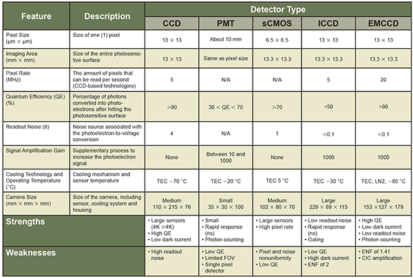
While these technologies can vary heavily from one manufacturer to another, presented here are the typical values one can obtain in scientific imaging. Despite their distinctive designs, each technology can be examined on the basis of common characteristics. These features, added to the performance of cooling and packaging technologies, alter either directly or indirectly the resolution, noise levels and detection probability. These are summarized in Table 1.

Table 1. Summary of the common features for the five most widespread imaging technologies currently available. Note that the data in this table is based on the average specifications of each technology, manufacturer notwithstanding. CCD-based technologies (CCD, ICCCD and EMCCD) sensor characteristics are for 1024 × 1024-pixel resolution sensors, while the sCMOS features come from 2048 × 2048-pixel resolution camera. TEC = thermoelectric cooling. ENF = excess noise factor. CIC = clock induced-charges. FOV = field of view.
Since life sciences applications frequently involve low-light conditions, camera noise becomes the limiting imaging factor. While the sensor’s electronics dictate the readout noise, the dark current is time- and temperature-dependent. It is often taken for granted that a camera’s dark current is negligible when performing short acquisitions, as it builds up slowly; therefore, deep cooling is unnecessary. It is indeed the case when a sample’s signal is strong enough. However, insufficient sensor cooling leads to degraded camera sensitivity in low-light conditions, even with short exposure time, as the dark current level matches the photoelectron signal.
Note that several camera features account for imaging performance. Identifying the application conditions is necessary to pinpoint these parameters. The following example illustrates how optimizing camera features leads to increased efficiency of the system.
Practical example
Selecting the best camera for a given application may turn into a series of costly trials and errors. Recognizing which detector offers the optimal features for a particular system saves both time and money. The development stages behind the design of a hyperspectral fluorescence-guided surgery device for brain tumor resection — which attained remarkable precision with the right camera — illustrate the importance of this process.
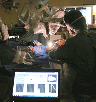
Advances in neurological navigation now enable surgeons to differentiate precisely cancerous brain cells from healthy ones during surgery, thus allowing for safe and complete tumor removal. One of these breakthroughs quantifies a fluorescent biomarker specific to a particular type of tumor and establishes the concentration levels above which it is safe to assume the tissue is malignant (Figure 1). In neurosurgery, the first fluorescent biomarker quantification system used a point detection probe and had proven to differentiate cancerous from healthy brain tissues with unprecedented accuracy.

Figure 1. An imaging system integrating a high-sensitivity camera to a neurosurgical microscope. The system superimposes images of brain tissues with their fluorescence signatures to identify malignant cells in real time. Courtesy of McGill University Health Center.
In spite of its impressive performance, having to manipulate the point detection probe during surgery can be a deterrent for the surgeon. It disrupts his surgical workflow, and the device’s poor field of view requires multiple acquisitions to scan the entire exposed brain surface. Even then, the surgeon may miss a cancerous pocket, therefore leaving malignant cells, which are likely to repopulate the patient’s brain.
This particular reason led to the design of a wide-field hyperspectral system to quantify the fluorescent biomarker, akin to the point detection probe, but with a larger field of view. Such a system would image the entire surgical cavity without obstructing the surgeon’s workflow. It coupled a CCD camera with a tunable filter to perform hyperspectral imaging and quantify the biomarker. However, CCD technology was limited by its sensitivity, as its read-out noise was too high. In order to collect enough signal to overcome the noise, the exposure time had to be prolonged; unfortunately, this proved to be too long under surgical conditions. The newly developed system could not reach the point detection probe efficiency level, even with longer acquisitions.
An sCMOS camera replaced the CCD to try to solve the issue2. The sCMOS technology has a lower readout noise than the CCD. In addition, the camera had a larger detector, or imaging area, and a greater readout speed. The upgraded system did indeed achieve improved results compared to the CCD camera but still could not detect cancerous cells with lower concentrations of biomarkers like the probe. Experiments were performed with longer acquisitions while only reading the central portion of the detector, as reading the sensor more slowly increases its sensitivity. Doing so negated the added benefits of the sCMOS.

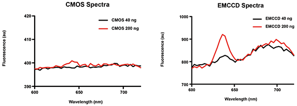
Figure 2. Examples of fluorescence spectra acquired with sCMOS and EMCCD imaging systems at 20-ms exposure. Each spectrum displays protoporphyrin IX (PpIX) fluorescence, the biomarker specific to malignant brain cells in this experiment, in concentrations of 40 and 200 ng/ml. The EMCCD camera detected over twice as many photons emitted through the PpIX fluorescence compared to the sCMOS camera for the same exposure time. Courtesy of F. Leblond/École Polytechnique de Montréal.
The system was then examined to compare its performance with a CCD, an sCMOS and an EMCCD camera. By evaluating the system’s requirement beforehand, one should have noticed that the prime limitation of the biomarker’s quantification with hyperspectral imaging is sensitivity: the ability to detect as many photons as possible. The EMCCD camera proved to be a fast and sensitive solution that allows real-time imaging during a surgical procedure. In this case, it is the ideal wide-field camera, as it possesses the lowest intrinsic noise. Indeed, when comparing the new EMCCD system to the sCMOS system on the same neurosurgical microscope — using a split light path — the former proved to be 20 times more sensitive than the second and yielded results similar to the probe system while imaging a larger field of view. In the end, the system could accommodate the surgeon’s need to image the entire exposed brain surface without missing the cancerous cells’ biomarkers that emit less light, and, in doing so, increase the chances of remission of the patient.
In this particular example, choosing the sCMOS sensor despite its larger detector size, faster readout speed and reasonably low readout noise made no sense, as it did not provide the necessary sensitivity. Indeed, the system did not benefit from the sCMOS’ strengths as it performed slow-speed measurements on a smaller region of the detector in order to achieve improved sensitivity. The EMCCD could have been initially preferred, had the research group developing the hyperspectral fluorescence-guided surgery system been more familiar with the imaging technologies at their disposal.
Ultimate sensitivity
When choosing an imaging system for a specific application, it is important to understand what level of performance is needed and what will be the limiting factor for obtaining the clearest, richest data. In some conditions, the signal arriving at the detector is so faint that it can barely be distinguished from the background noise, as was the case for the fluorescence-guided brain tumor resection. Despite their performance, neither the CCD, PMT, sCMOS nor ICCD technologies could adequately discriminate single photons from the noise, even when noise sources had been minimized altogether.

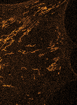
Figure 3. Side-by-side comparison of living cell images illustrating the increased details a more sensitive camera reveals with a superior SNR. At left, an image of a cell taken with a commercially available EMCCD camera at −65 °C (lowest advertised minimum for this camera model) and an EM gain of 1200 (maximum allowed by the camera). The acquisition was performed without photon counting and displays the camera’s high excess noise factor (ENF) — see Table 1. At right, the same cell imaged with Nüvü Cameras’ EMCCD camera at −85 °C and an EM gain of 5000. This time the acquisition was performed in photon-counting mode, which suppresses ENF3. Courtesy of Quorum Technologies Inc.
However, with its enhanced sensitivity, the EMCCD technology was right for this application since it can detect an incoming signal of less than one photon per pixel per second, while acquiring several images per second. For applications that involve extreme low-light conditions, the EMCCD camera can become an effective wide-field photon-counting imaging device3 because of its low noise floor. Figure 3 shows another example of an application limited by the low intensity of the incoming signal. The added sensitivity of an imaging system with photon counting capabilities made it possible to identify more clearly intracellular structures and even brought to light objects that were indistinguishable with a noisier camera.
From fluorescence microscopy to Raman spectroscopy, low-light life sciences applications can make a leap forward with photon-counting imaging, reaching the ultimate sensitivity. The technique yields unprecedented SNRs in faint flux conditions, unraveling new cellular features and decreasing biomarker concentration detection thresholds and illumination intensity needs, thereby pushing medical diagnosis and treatment to a new level of accuracy when only a few photons are observable.
Meet the authors
Myriam Francoeur is technological marketing expert at Nüvü Cameras in Montreal; email: [email protected]. Yoann Gosselin is an applications engineer at Nüvü Cameras; email: [email protected].
References
1. A.G. Basden (July 2015). Analysis of electron multiplying charge coupled device and scientific CMOS readout noise models for Shack-Hartmann wavefront sensor accuracy. Astron Telesc Instrum Syst, Vol. 1, Issue 3, pp. 039002-1–10.
2. P.A. Valdes et al. (August 2013). Through-microscope spectroscopic excitation and emission for fluorescence molecular imaging as a tool to guide neurosurgical interventions. Opt Lett, Vol. 38, pp. 2786–8.
3. G. Crétot-Richert and M. Francoeur (October 2014). Applications expand for photon counting. Photonics Spectra, Vol. 48, Issue 10, pp. 43-46.
DETECTOR TECHNOLOGY OVERVIEW
CCD, PMT, sCMOS, ICCD and EMCCD technologies have different sensors and electronic architectures. All sensors convert photons into photoelectrons via the photoelectric effect. The operations following the conversion, outlined below, distinguish the technologies.
• A CCD transfers accumulated charges from one pixel to the next by applying a series of voltage variations. Photoelectrons are displaced to a shift register then read out.
• A PMT is a single-pixel detector. Photoelectrons are accelerated through a high-tension vacuum tube containing multiple stages; upon impact, the charges ionize new electrons that hit other stages through an avalanche effect, hence amplifying the electron signal before readout.
• In an sCMOS, each pixel is read out individually after collecting photoelectrons. Widely used in most digital cameras, the CMOS technology has also been adapted for scientific use (thus the ‘s’ in the sCMOS acronym) by implementing more sophisticated parallel reading amplifiers that optimize the sensor readout depending on the incoming signal.
• The ICCD combines both PMT and CCD technologies. A photodiode converts photons into electrons, which are accelerated toward a phosphorus scintillator in a high-tension vacuum tube. The latter converts the electrons into photons that a CCD detects.
• EMCCD technology operates similarly to a CCD but amplifies the electron signal with an added impact ionization, or electron-multiplying register, built into the sensor.