Jean-Michel Pelaprat and Dr. Baishi Wang, Vytran LLC
Optical fiber probes are still in the early stages of manufacturing, but filament fusion technology enables many probe designs, from ball lenses to fiber lenses, among others. Cleaving fiber bundles with high quality and good throughput facilitates their manufacturing and provides a cost-effective solution for device makers.
Optical fiber components have been widely used in optical communication, fiber laser systems, fiber optic gyroscopes and fiber sensing applications. Recently, fiber optic probes have been adopted for in vivo optical imaging of internal tissues via optical coherent tomography (OCT), a technology used for morphological imaging of biological systems such as the retina, vasculature and gastrointestinal tract.1 OCT interferometrically measures the phase delay of an injected light beam2,3 onto a measured surface. As a result, the cross-sectional internal microstructure of architectural morphology can be “visualized” at high resolution in micron scale.
The main advantages of using fiber optic probes in OCT are: (1) high spatial resolution at the micron level, wherein the optical resolution is mainly determined by the numerical aperture of the focusing objective; (2) cost-effectiveness, thanks to high-volume manufacturing at low cost via fiber fusion technology; and (3) technological flexibility with measurement in either time or frequency domain or via 1-D1,4 or 2-D5,6 methods.
Implementation and fabrication of these probes require stable and well-controlled fiber fusion and glass processing technologies. Automation is a must for consistent and cost-effective mass production of such devices. Furthermore, precision fiber cleaving enables the accurate, clean and cost-effective cuts required for creating the fiber image guides used in different varieties of endoscopes.
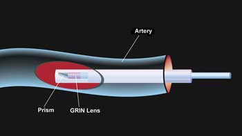
Figure 1. A “window” view of a 1-D fiber optic probe inside an artery. Images courtesy of Vytran LLC.
Fiber optic probes
For medical imaging applications, fiber optic devices can be categorized as 1- or 2-D probes. Measurements usually are made either coherently via an interferometer to obtain the phase information or incoherently to acquire the intensity information. In OCT imaging, 1-D coherent fiber optic probes deliver a focused beam to the surface of an internal organ to make a point-wise measurement of the phase or time delay of the delivered beam relative to its reference beam. Figure 1 is an illustration of this type of probe for OCT imaging. To extract the 3-D morphological information, the probe is rotated and pulled back simultaneously; 3-D imaging of the internal structure can then be realized.
Figure 2 shows an example of this type of optical probe. Typically, light at a wavelength of approximately 1300 nm is delivered from a superluminescent light-emitting diode source through a single-mode fiber. The beam is expanded via a section of graded index (GRIN) fiber lens. The beam is deflected by a microprism mounted at the end of the fiber tip and is then delivered to the surface being analyzed. The beam reflected from the surface is re-collected by the probe and coupled back into the fiber. This beam is made to interfere with a reference beam so the phase or time delay information can be extracted. Via this method, the morphology of the internal organ surface can be quantitatively measured. Spatial resolution of the measurement is determined by the spot size of the focused beam, usually around a few microns. A variation of this type of probe includes using a different GRIN lens and adding a spacer (usually coreless fiber) between the GRIN lens and the optical fiber. Multiple GRIN lenses can be used to achieve different optical properties of the output beam.
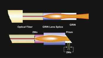
Figure 2. A schematic of a 1-D fiber optic probe.
Fabricating probes
The key optical properties of a fiber optic probe similar to the one shown in Figure 2 are focusing spot size and working distance, both of which are determined by the numerical aperture and aberration introduced by the focusing lens. In addition, any backreflection from the optical interface must be suppressed to enhance the signal-to-noise ratio. Mechanically, the probe has to be rugged for long-term stability and immune to vibration.
It is preferable to make this type of probe all-fiber using high-quality fusion splicing rather than the conventional free-space optics approach. This provides some distinct benefits: First, an all-fiber probe does not require any alignment; it is also more compact. Second, a fusion-spliced fiber joint significantly reduces the backreflection and improves the transmission efficiency. As a result, a better measurement signal-to-noise ratio can be achieved. Third, an all-fiber device is more rugged and intrinsically immune to ambient mechanical vibration and temperature change. Overall, it is more reliable, consistent and cost-effective.
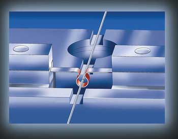
Figure 3. A schematic of the filament fusion process.
Optically, the quality of the focusing beam is crucial for the imaging system to maintain high spatial resolution and good measurement sensitivity. For an all-fiber device, this translates to a need for uniform heating around the fiber during the fusion process to maintain good beam circularity. Also, the GRIN fiber length must be precisely controlled to deliver the desired optical properties of the exit focusing beam.
When fabricating these fiber optic probes, filament fusion technology (Figure 3), which is based on resistive heating, provides several advantages. First, the filament has a circular shape, which maintains a uniform temperature circumferentially and therefore leads to uniform heating around the fiber. Second, filament fusion offers temperature control over a wide range, which is important for processing different types of fiber with various optical characteristics or doping concentrations. Third, filament fusion is highly consistent and repeatable. This translates to a stable process and high production consistency and yield. Fourth, filament fusion produces a strong splice between fibers with splice strength typically exceeding 200 kpsi. This ensures long lifetime and robustness of the probe.

Figure 4. Left: A schematic of several sections of fiber fused together. Right: A side view shows actual fused fibers spliced using filament fusion and precise length control of the fibers.
During the fusion process, control of the GRIN fiber length is critical to achieving the desired optical characteristics of the output beam. Position registry between fiber splicing and cleaving is required to precisely control the length of each spliced fiber pair. Figure 4a schematically shows several sections of fibers that are spliced together; Figure 4b is the side-view image of four sections of fibers with different fiber lengths spliced together. The output fiber is cleaved at an angle to suppress backreflection.
Figures 5a and 5b show additional examples of fiber optic probes. The former shows a fiber optic probe with a ball lens tip; the latter, an encapsulated probe with several fiber elements spliced together inside the capillary tube.

Figure 5. Left: A fiber optic probe with a ball lens at the tip. Right: A complete all-fiber probe with capillary tube encapsulation.
Image guides
In addition to using the 1-D pointwise fiber probe for OCT, the fiber bundle, consisting of several thousands of micron-level fibers compactly arranged together, is often used as an image guide for 2-D coherent imaging.6
Figure 6 is a schematic of such a fiber imaging system based on a Michelson interferometer configuration. The measurement typically is made in time domain using a broadband source or in frequency domain using a tunable swept laser source to extract the 2-D phase information.
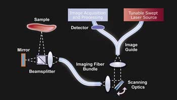
Figure 6. A 2-D coherent fiber bundle imaging setup based on Michelson interferometry.
One important aspect for producing this type of system is how to process the end face of the fiber bundle, which works as a pathway to transmit thousands of light beams through. High optical quality of the bundle end face is critical to ensure good visibility of the interference fringes and therefore good performance of the system. Polishing is typically used for producing a high-quality flat surface on the bundle end face. However, this is labor-intensive and time-consuming, and polishing tends to have a rounding effect around the edge, which could compromise surface flatness.
Alternatively, advanced fiber-cleaving techniques, such as the tension-scribe method, can be used to produce a mirrorlike flat end face on fibers with various diameters. The tension-scribe fiber cleaving method is schematically shown in Figure 7. During the cleaving process, a predetermined tension (based on the fiber’s diameter) is applied to generate tensile stress in a longitudinal direction. A blade scribes the fiber vertically from the side to create a crack. When a large enough crack forms, the fiber can be cleaved to produce a clean, high-quality fiber end face. Embedded processes can precisely control the cleaving process and make it fully automatic. This method requires a special fiber cleaver such as the LDC-400 Large Diameter Cleaver from Vytran LLC.

Figure 7. A schematic of the tension-scribe fiber-cleaving method.
The whole tension-scribe cleaving process takes less than 30 seconds and produces a surface with flatness generally better than a polished surface. It can also maintain a small cleave angle, which minimizes the deflection of the input and output beams.
Additionally, low cleave angle is important for high-quality splicing if the cleaved fibers are to be fusion spliced together.
This method can be readily used for cleaving image guides, whose size can be more than 1 mm in diameter with several thousands of fiber pixels. Figure 8 shows an example of a cleaved bundle. The bundle diameter is 670 µm with 10,000 fiber pixel count.
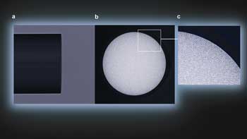
Figure 8. Images of a cleaved fiber bundle with 670-µm diameter: (a) side view of a flat cleave angle; (b) end view of the same cleaved bundle; (c) close-up view of the fiber bundles.
All-fiber based probes have demonstrated technical superiority for both 1- and 2-D optical imaging in OCT applications. Although fiber probes are still in the early stage of manufacturing, market demand will grow exponentially in the years to come. Unique filament fusion technology is enabling many probe designs, from fiber lenses to ball lenses and many others. The capability of cleaving fiber image bundles with high quality and good throughput facilitates their manufacturing and provides a cost-effective solution for device makers. Fully automated fiber fusion systems based on filament fusion and tension-scribe technology could allow low-cost, high-volume manufacturing of these fiber optic probes for medical applications.
Meet the authors
Jean-Michel Pelaprat is CEO of Vytran LLC, and Dr. Baishi Wang is its director of technology; email: [email protected].
References
1. G.J. Tearney et al (1996). Scanning single-mode fiber optic catheter-endoscope for optical coherence tomography. Opt Lett, Vol. 21, p. 543.
2. J.G. Fujimoto et al (1999). High resolution in vivo intra-arterial imaging with optical coherence tomography. Heart, Vol. 82, p. 128.
3. Y.X Mao et al (2008). Fiber probes used in optical coherent tomography. SPIE Proc 7099, Photonics North.
4. X. Li et al (2000). Imaging needle for optical coherence tomography. Opt Lett, Vol. 25, pp. 1520-1522.
5. T.Q. Xie et al (2006). GRIN lens rod based probe for endoscopic spectral domain optical coherence tomography. Opt Expr, Vol. 14, p. 3238.
6. H.D. Ford and R.P Tatam (2009). Swept-source OCT with coherent imaging fibre bundles. 7503, 20th International Conference on Optical Fibre Sensors, Julian Jones et al, eds.