Moshe Bril, !%Holo-or Ltd.%!
Fractional laser skin treatment, also known as fractional photothermolysis, is a relatively new method of skin rejuvenation in which the targeted areas of the skin are precisely spaced out at a microscopic level. In between, some skin is left perfectly intact while other zones are laser-treated. The effect is visually comparable to pixels in digital images. The small spots of treated skin replace old destroyed cells with new healthy ones, and the untreated areas maintain the tissue’s stability for quicker recovery.
Fractional laser skin treatments can use the intense energy of ablative or skin resurfacing lasers, while providing the greater safety and faster recovery time of lower-energy, nonablative laser treatments. As a result, patients can undergo a relatively risk-free procedure and achieve the skin rejuvenation they desire quickly. There is less worry about scheduling the many follow-up treatments associated with most low-energy laser options.
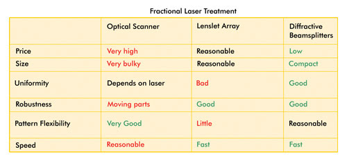
 Comparison of the three major techniques of fractional laser treatment. Green is best; red is worst.
The approach is gaining popularity in the market and has certain benefits over conventional laser skin treatment, including faster recovery of the skin. There are a few ways to obtain the special pixel-type beam profile required for this treatment.
There are three major technologies for achieving the desired patterned profile: optical scanners, lenslet arrays and diffractive beamsplitters. In this article, we will mention some differences between these and compare their benefits, describe some design considerations for diffractive beamsplitters and look at the advantages of a new development in this field: 1 x 37 hexagonal-type splitters.
Optical scanners consist of a fast-moving mirror on top of a galvanometer. The pattern can be flexible and can be determined by the software that drives the galvanometer. The disadvantages of this method include its high cost and the bulkiness of the system. Also, the moving elements can fail, and the mirror can be damaged. The spots are projected one after the other, so this procedure is relatively slow, and the uniformity depends upon the pulse-to-pulse stability.

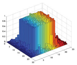
Typical uniformity between the beams in a diffractive beamsplitter.
Lenslet arrays consist of a two-dimensional array of diffractive or refractive lens elements. The incoming beam is focused at a nearby point in a fixed array of 7 x 7 or 9 x 9 or any other number – that is, each element will generate the quantity of numbers for which it is designed. Because the incoming beam is typically not uniform (and has a Gaussian or other shape), the uniformity of the spots on the treated surface is not good. This can be overcome by adding a homogenizer, but then the system becomes bulky and expensive. The working distance is not flexible, and customization is expensive. It is very difficult to create these arrays in exotic materials such as the ZnSe and sapphire needed for wavelengths between 2500 and 11,000 nm.
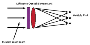
The diffractive beamsplitter is gaining in popularity because it combines the advantages of both older techniques. The energy input beam is projected to parallel beams separated by an angle. If a lens is placed after this element, a spot array will appear in the focal plane of the lens.

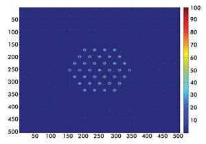
Conceptual image of a 1 x 37 spot array. Numbers represent pixels.
Each spot in the array will get energy from the complete input diameter. Therefore, even if the laser beam has a nonuniform profile or is Gaussian, each of the spots will still get the same energy.
It is quite easy to change the pitch of the spots and working distance. The only thing needed is to change the working distance. Companies like Holo-Or already have a large collection of standard designs, and making a custom design is quite inexpensive. The elements are robust and are available in fused silica, sapphire and ZnSe. These arrays start from 4 x 4 and go up to 9 x 9. Arrays like 6 x 8 and 5 x 7 are also available.

Conceptual generation of spots from a diffractive beamsplitter and a lens. Images courtesy of Holo-Or Ltd.
With diffractive elements, some attention must be given to the center spot. In the center of the pattern, some intensity can always arise. For an “even number by even number” design, this will fall outside the location of the desired spots. Therefore, most designers will prefer to choose an “odd number by odd number” (or hexagonal) array, where the center is a desired spot. But even for these odd-by-odd designs, the intensity of the center spot should not be higher than the intensity of the other spots. Holo-Or has developed a technology that overcomes this and typically guarantees for most designs that the center spot will not be stronger than the average of the other spots. This technology is part of the pattern design and is included in most of the designs manufactured by Holo-Or.
Most recently, Holo-Or introduced hexagonal splitter arrays for this application, with 19 or 37 spots arranged in a hexagonal shape. The clinical advantage with this shape is that each spot is positioned equidistant to its neighbors.
Meet the author
Moshe Bril is a physicist who is responsible for sales and marketing at Holo-Or Ltd. in Rehovot, Israel; e-mail: [email protected].