To achieve temperatures and pressures similar to those at the center of the sun, the National Ignition Facility will employ a new optical switch technology -- the plasma-electrode Pockels cell.
Camille Bibeau, Mark A. Rhodes and L. Jeffrey Atherton, Lawrence Livermore National
The world’s largest laser, the National Ignition Facility (NIF) at Lawrence Livermore National Laboratory in Livermore, Calif., is 85 percent complete (Figure 1). When operational, its 192 ultraviolet beams will converge on a target filled with frozen hydrogen, enabling scientists to observe the behavior of materials at temperatures and pressures never before achieved and to study the physics of inertial-confinement fusion.
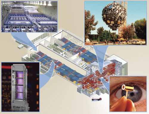
Figure 1. This schematic of the 192-beam National Ignition Facility shows (clockwise from bottom left) a plasma-electrode Pockels cell, the interior of the laser bay, the target chamber and a hohlraum target.
Generating the 1.8 MJ of laser energy needed to produce conditions similar to the center of the sun required that NIF deviate from the traditional, single-pass amplifier layout in which a beam passes only once through each consecutive amplifier stage and, consequently, that many new technologies be developed.1
Single-pass amplifier layouts have been used successfully for decades, and they remain the architecture of choice for many applications because of their simplicity. Until the NIF, all the lasers built for inertial confinement fusion research at Livermore also employed the single-pass design. Typically, the beam in this approach is increased in size after each amplifier stage, using an expanding telescope to keep the fluence, or energy per unit area, below the damage threshold of the optical components.
This layout, however, can lead to long beam lines, awkward beam bundling and the need for a large number of optical components. Furthermore, each amplifier and telescope stage requires a different design, which drives up the parts count. A single-pass system also is not particularly efficient because the laser beam travels through each amplifier stage only once and may not fully saturate the gain available in the stages.
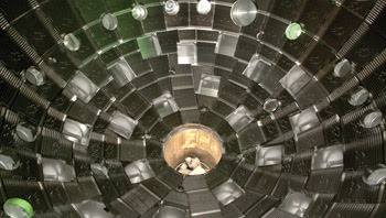
Two technicians are transported via a computer-controlled precision lift into the center of the 10-m-diameter National Ignition Facility target chamber to install protective panels.
In the early planning stages for the NIF, it was decided that a new architecture was needed to reduce the cost and part count and to simplify the physical layout. Therefore, the facility will use a multipass power amplifier design, which maximizes performance by passing a beam through the amplifiers several times.
The configuration of the NIF as a multipass system was enabled by the invention of the plasma-electrode Pockels cell.2 As a result, the beam line can be folded, reducing the total path by almost 250 m compared with the single-pass configuration (Figure 2). Because the main and power amplifier assemblies are nearly identical in hardware design, the commonality of optics and mechanical hardware minimizes the overall quantity of distinct parts. Also, because the beam passes multiple times through both amplifiers, energy is efficiently extracted. Consequently, the electrical-to-optical efficiency was increased by more than a factor of five compared with the previous, 10-beam system.

Figure 2. The National Ignition Facility is a multipass oscillator-amplifier laser system. The system injects a seed beam into the beam transport optics. The beam passes once through the power amplifier and into the main amplifier cavity, where it remains for four passes before being ejected. It then makes one final pass through the amplifier before entering the final optics assembly, which includes the frequency-conversion crystals, phase plates and focusing optics. The clustered beams are focused into the 10-m-diameter target chamber onto a cryogenically cooled target.
The plasma-electrode Pockels cell also plays an important role in the reduction of unwanted amplified light. High-energy fusion laser systems are designed to properly manage stray reflections and parasitics, amplified laser light traveling in the wrong direction at the wrong time. In the NIF layout, light generated by reflections from optics or spontaneous emission from the amplifiers can make, at most, only two passes through the main amplifier, and it therefore never builds up to dangerous energy levels.
Scaling Pockels cell technology to meet the 1600-cm2 aperture size, square shape and 5-J/cm2 energy density specifications of the NIF laser required an optical switch of unprecedented proportions. Each cell had to be scaled from the 2 to 3 cm in diameter that is typical of commercial devices to the 40 × 40-cm aperture in the NIF beam line. Conventional ring-electrode Pockels cells do not scale to such large apertures or to the square shape needed for close packing of multiple beam lines.
To achieve a reasonably uniform electric field distribution in the crystal of conventional Pockels cells, the crystal’s aspect ratio (i.e., of its diameter to its length) must be no greater than 1. But the required aperture for the NIF is 40 cm, and a crystal that long would result in excessive optical absorption, strain depolarization and cost. Alternative geometries that combine thin crystals with transparent, conductive thin films on the crystal surfaces to serve as electrodes have low damage thresholds and exhibit insufficient conductivity to meet the system’s switching requirements.
Cell technology
The plasma-electrode Pockels cell technology developed for the NIF provides an alternative that scales in aperture size and endures higher fluences.
The plasma-electrode Pockels cell technology was invented at Livermore in the 1980s, but it was first used in a high-energy beam in 1990. A 37-cm-aperture prototype was successfully demonstrated in 1995 for a project called Beamlet, which was the scientific prototype of the NIF.3,4
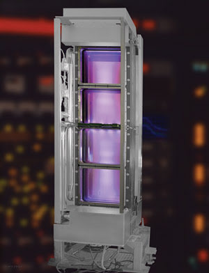
Figure 3. The plasma-electrode Pockels cells are arranged in a 4 × 1 modular configuration. Each assembly weighs approximately 800 kg and measures 2.6 × 0.9 × 0.62 m.
The next evolutionary step in the design required finding a way to closely pack multiple apertures to meet the beam-bundling needs. Most NIF components are designed to be “play and plug,” enabling them to be easily replaceable for serviceability and in the event of a malfunction. For the plasma-electrode Pockels cells, the smallest replaceable unit is an array of four of the devices arranged in a vertical line (Figure 3). Altogether, 48 of these units provide optical switching for the NIF’s 192 beam lines. Each of the four apertures requires two fused-silica windows and one plate of potassium dihydrogen phosphate (KDP). Auxiliary pulsed-power systems include four plasma-pulse generators and two switch-pulse generators.
Figure 4 shows a side view of a plasma-electrode Pockels cell in cross section and a simplified scheme of the required external electronic circuit. For scale, the dimensions of the KDP crystal are 41 × 41 × 1 cm. Vacuum regions on each side of the crystal are filled with a working gas (He + 1% O2) at an optimized pressure of 60 to 70 millitorr.
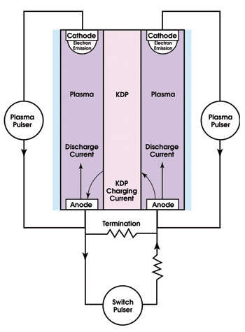
Figure 4. A side view shows the plasma-electrode Pockels cell and its associated electronic circuit. The plasma pulsers produce the plasma electrodes by high-current discharge in helium, and the switch pulser applies the switching voltage across the KDP crystal.
With a high-current pulse, the plasma pulsers create a cloud of ionized gas, or plasma, from an electric discharge formed on both sides of the crystal. The plasma between the KDP and the fused silica window forms the electrodes in the cell.
Voltage from the switch pulser is applied across the crystal via the plasma electrodes and allows the surface of the crystal to electrically charge in approximately 100 ns, with very high uniformity across the aperture. The plasmas are transparent at the laser wavelength, so they have no effect on the high-power laser beam passing through the cell. As in a conventional Pockels cell, if the potential difference across the crystal is V90 (i.e., the λ/2 voltage), the polarization of an incoming linearly polarized beam is rotated by 90°.
The plasma is created in a two-stage process: a low-current preionization (or “simmer”) discharge and a high-current pulse discharge. The simmer stage provides a low-level constant current of 30 mA, so the current path is well-established when the high-current pulse arrives.
During the discharge, helium ions from the plasma are accelerated by the discharge potential, and they bombard the cathode, producing electrons by secondary emission. The electron emission sustains the discharge. However, the ion bombardments also lead to sputtering of the cathode material, which can leave deposits on the crystal and window surfaces, reducing their optical damage threshold.
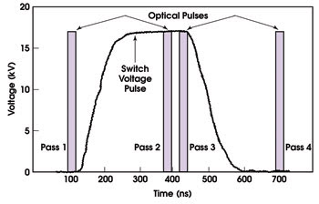
Figure 5. This diagram shows the temporal relationship between the voltage pulse applied to the plasma-electrode Pockels cell and the four passes of the laser pulse within the main amplifier cavity.
To eliminate this deposition, the cathode surfaces are made from high-purity graphite, so the sputtered material is carbon. The carbon reacts with the oxygen in the plasma to form CO and CO2, which are siphoned out with a vacuum system. The vacuum and gas system provide the required environment inside the plasma-electrode Pockels cell for optimum formation of the plasma electrodes. The gas feed system injects the discharge gas mixture near the anodes, so that it flows across the crystal faces, and active feedback control maintains the gas pressure.
The switch-pulse generator produces a nominally rectangular pulse. The switch pulser must satisfy several NIF requirements, including shot-to-shot jitter of less than 2 ns and a voltage flattop at least 100 ns long within ±2 percent of V90. The switch pulser can charge the KDP crystal to a V90 voltage of 16.4 kV or discharge it from V90 back to 0 V in approximately 100 ns.
Switch modules
An NIF optical switch module consists of a plasma-electrode Pockels cell and a polarizer that reflects one polarization and that transmits the other.5 The Pockels cell and polarizer function together as a switch that “closes” to trap the optical pulse in the amplifier cavity for four gain passes and then “opens” to divert the optical pulse out of the amplifier cavity (Figure 6).
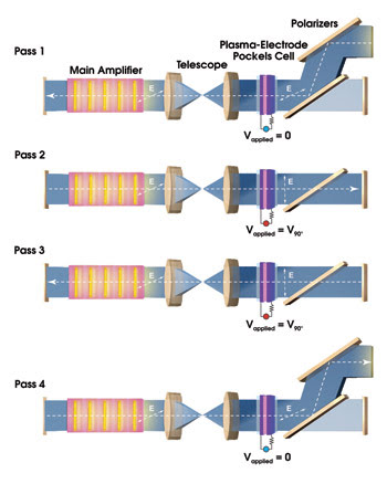
Figure 6. A pulse makes four individual passes through the Brewster-angled slabs in the main amplifier. It is injected into the amplifier cavity by reflecting off two polarizers. The voltage on the Pockels cell is turned on to rotate the polarization by 90° to trap the beam in the cavity for two more passes. On the fourth pass, the voltage on the Pockels cell is switched to zero, and the beam exits the cavity.
In this configuration, it is important that the transmission of the cell is high when the optical pulse is trapped and that the polarization rotation is uniform to efficiently switch the beam out of the cavity. In addition, the cell must switch from an “open” to a “closed” mode on a 100-ns timescale. The temporal relationship among the optical pulses and the switch pulse is shown in Figure 5.
The performance of a 4 × 1 plasma-electrode Pockels cell module is evaluated by measuring the extinction ratio for each cell for both the open and closed operation modes.6 In an offline setup, a cell is placed between a pair of polarizers. A beam-expanding system and a CCD camera are used to capture 2-D images of a test beam passing through the optics.
To test the open mode, the cell voltage is off, and CCD images are compared with and without the final polarizer rotated. To test the closed mode, both polarizers are kept aligned, and CCD images are compared with and without the voltage on the cell. The NIF requires the extinction ratio for each individual aperture to be greater than 100 (i.e., 99 percent of the light is in the proper polarization), while the worst location can have an extinction ratio no lower than 50 (i.e., 98 percent of the light being correctly polarized).
The average and minimum extinction ratios measured for these tests on all passes have easily met the NIF requirements. In the “closed” mode, the average ratio ranged between 460 and 1032, and the minimum ranged between 108 and 164. In the open mode, the figures were 471 to 821 and 110 to 151, respectively. Furthermore, these are very reproducible, with a shot-to-shot variation of less than 10 percent.
Although the plasma-electrode Pockels cells are impressive in themselves as the world’s largest optical switches, they are only 48 of 6200 components in the NIF. Each component, designed for easy replacement when necessary, is a complex module containing sophisticated optics and instrumentation. Because each weighs between 500 and 1000 kg, large robotic forklifts are used to gently insert them into the beam lines from below.
The laser system as a whole is staggering in its scale, being composed of more than 3000 40-kg slabs of laser glass, 26,000 smaller glass optics, 3000 laser mirrors and more than 1000 crystalline optics, including the 48 Pockels cell units. More than 7600 of the largest flashlamps ever built, each of them 2 m long, will energize the amplifiers.
The NIF’s arena-size building houses 192 laser beams, designed to deliver up to 1.8 MJ of ultraviolet laser energy and 500 TW of power to millimeter-size targets at the center of its 10-m-diameter target chamber. Scientists around the world are anticipating the first set of ignition experiments — slated to begin in 2010 — in which the laser pulses will compress a deuterium-tritium target to conditions in which it will ignite and burn, liberating more energy than is required from the laser to ignite the fusion reactions. The experiments will be conducted in a well-controlled laboratory setting to study physical processes of temperatures and pressures approaching 108 K and 1011 atmos.
Acknowledgments
The authors would like to recognize Phillip A. Arnold, Peter J. Biltoft, David H. Roberts and the NIF development, engineering and operations teams of Lawrence Livermore National Laboratory and Julius Goldhar of the University of Maryland, College Park, for their significant scientific and engineering contributions.
This work was performed under the auspices of the US Department of Energy by the University of California, Lawrence Livermore National Laboratory, under Contract W-7405-Eng-48.
Meet the authors
Camille Bibeau is a laser physicist in average power laser development and strategic program planning with the National Ignition Facility Program; e-mail: [email protected].
Mark A. Rhodes is a pulsed-power electric engineer previously with the NIF Program and now with the Beam Research Program; e-mail: [email protected].
L. Jeffrey Atherton is a program manager for materials science and technology with the NIF Program; e-mail: [email protected].
The authors all are with Lawrence Livermore National Laboratory in Livermore, Calif.
References
1. G.H. Miller, E.I. Moses and C.R. Wuest (December 2004). The National Ignition Facility: enabling fusion ignition for the 21st century. NUCL FUSION, pp. S228–S238.
2. J. Goldhar and M. Henesian (July 1986). Large-aperture electrooptical switches with plasma electrodes. IEEE J QUANTUM ELECT, pp. 1137-1147.
3. M.A. Rhodes et al (August 1995). Performance of large-aperture optical switches for high-energy inertial-confinement fusion lasers. APPL OPTICS, pp. 5312-5325.
4. M.A. Rhodes et al (December 1995). Plasma electrode Pockels cell for ICF lasers. Proc. SPIE, Vol. 2633, Solid State Lasers for Application to Inertial Confinement Fusion (ICF), pp. 94-104.
5. P.A. Arnold et al (May 2004). Deployment, commissioning, and operation of plasma electrode Pockels cells in the National Ignition Facility. Proc. SPIE, Vol. 5341, Commercial and Biomedical Applications of Ultrafast Lasers IV, pp. 156-167.
6. M.A. Rhodes et al (July 1999). Plasma electrode Pockels cell for the National Ignition Facility. Proc. SPIE, Vol. 3492, Third International Conference on Solid State Lasers for Application to Inertial Confinement Fusion, pp. 144-147.
How a Pockels Cell Works
First described in 1906 by Friedrich C.A. Pockels, the linear electro-optic effect behind the operation of a Pockels cell occurs in crystals that lack a center of symmetry. It is observed as a linear change in refractive index produced by an applied electric field.
Properly biased, a Pockels cell acts like a wave plate, retarding one polarization relative to the other and thereby producing an effective rotation of the polarization direction. Electro-optic materials often used for Pockels cells include ammonium dihydrogen phosphate (ADP), potassium dihydrogen phosphate (KDP) potassium dideuterium phosphate (KD*P) and lithium niobate (LN).
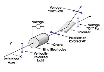
When polarized light passes through a properly biased and oriented Pockels cell, the polarization is rotated by 90°. In this case, the beam is reflected from the polarizer and switched out of the beam path.
A l/2 voltage is defined as the voltage (in the range of several kilovolts) that must be applied to the crystal to rotate the polarization by 90° (see figure). In laser systems, a Pockels cell and polarizer often are used in combination. Depending on the polarization state defined by the applied voltage on the Pockels cell crystal, the beam will be either reflected or transmitted by the polarizer. This combination of a polarizer and electrically controlled Pockels cell can switch the beam direction in billionths of a second.
When the electric field is applied orthogonal to the light path, the Pockels cell is said to be in a transverse configuration. When the electric field is applied along the light path, the Pockels cell is said to be longitudinal. Longitudinal Pockels cells are better-suited to large-aperture systems that do not require high-frequency modulation of the voltage. KDP and KD*P can be grown to >40 cm and are the only crystals available that can be used for such systems.