Advanced spectrophotometry accurately measures reflectance and transmittance properties of thin glass sheets.
TREVOR VOGT, GAMMA SCIENTIFIC
Thin-film coatings have long been ubiquitous in precision optical systems, and are now finding increasing use in eyeglasses, architectural glass and displays. When fabricating precision optics, the primary requirement is that coatings meet particular reflectance and transmittance specifications. But in consumer applications manufacturers are often concerned with the visual appearance and consistency of the coating. While instruments for quantifying coating appearance have been available for decades, legacy technologies suffer from two important limitations: as lab instruments, they are not suitable for production settings, and they often can’t accurately measure very thin glass sheets that are now finding greater use in displays.
Eliminating variations in touch-screen display coatings
In all capacitive touch-screen displays for tablets and cellphones, glass forms the topmost layer. Uncoated glass reflects about 4 percent of the incident light at each air/glass interface (at normal incidence). This relatively low reflection is still sufficient to be visually distracting and can make the display substantially harder to read in high ambient light. So users will often increase display brightness, wasting precious battery power. An antireflection coating to the outer glass surface can solve these problems.
When viewing the reflection of white light illumination, virtually all antireflection coatings appear to have a color cast. The color depends strongly on the exact thicknesses and indices of refraction of the individual coating layers. Even slight variations in these parameters that don’t push coating performance out of specification in terms of overall reflectance and transmittance values can alter the reflected color in a way perceptible to the eye. As a result, batch-to-batch variations in reflected color are routine in antireflection coatings.
These variations in perceived coating color are objectionable to display manufacturers that typically want a product that is visually consistent, and conforms to cosmetic standards that correspond with their brand image. The result is a need to measure the visual appearance of antireflection coatings, a task that requires photometric, as opposed to radiometric, measurements.
Quantifying emissivity in modern architectural glass
The common glass window has taken a decidedly high-tech turn over the past few decades. In particular, so-called low emissivity glass, or low-e glass, is now widely used in both commercial and residential “green construction” (emissivity is the ability of a material to radiate thermal energy).
Low-e coatings pass visible light and reflect some portion of the infrared spectrum. This greatly improves the insulating properties of the glass. Specifically, low-e coatings block heat from entering during summer months, and retain heat generated inside the building during the winter. It’s also common for low-e coatings to incorporate some ultraviolet light blocking. This minimizes fading and damage to fabrics, carpeting and wall coverings used within buildings.
Glass coatings that reflect some portion of the visible spectrum are also extensively employed, and buildings that incorporate this mirrorlike glass are a commonplace sight throughout the world. These coatings, which can be engineered to appear virtually any color on reflection, are used as an aesthetic architectural design element and sometimes to enhance occupant privacy.
For architectural glass intended to reflect a significant amount of visible light, perceived coating color is of particular concern. This is because a building is constructed of numerous separate panes of glass. Without a high degree of unit-to-unit color consistency, the building will look like a checkerboard, or patchwork quilt. Thus, architectural glass manufacturers
must measure the radiometric characteristics of their product to meet specified low-e performance, as well as to characterize its visual (photometric) appearance.
Color measurement basics
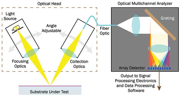
The main optical elements of a system for measuring surface reflectance are shown in Figure 1. A source is projected at a non-normal angle of incidence on to the surface under test. For measurements spanning the near-ultraviolet through the
near-infrared, this source is usually a halogen bulb. Collection optics, positioned exactly opposite the angle of incidence, focus the specular reflected light into a fiber optic cable. Most instruments allow the angles of incidence and collection to be widely adjusted to increase measurement flexibility.

Figure 1. Main functional optical elements of a spectrophotometer. Photo courtesy of Gamma Scientific.
The fiber feeds into an optical multichannel analyzer (OMA), which is a spectrometer that reports the reflectance intensity as a function of wavelength. However, this spectral reflectance data doesn’t quantify how an object appears to the human visual system (its perceived color). Even minor changes in the radiometric spectrum can affect the human experience of color.
Representing color in a way that correlates well with human visual experience requires working in a calibrated color space,
such as those defined by the International Commission on Illumination (CIE). The spectral data from the OMA is therefore mathematically converted into colorimetric tristimulus values, which can then be mapped into any one of the numerous CIE color spaces.
Advanced coating measurement technology
This spectrophotometer technology has been commercially available in a variety of different forms from a number of manufacturers for decades. It is effective and well-proven. However, all past product embodiments have had some combination of practical limitations that prevented their use in high-volume, commercial inspection applications.
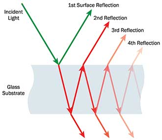
One significant drawback of some systems is that their optics collect light from one or more of the many multiple reflections that occur in a glass component, when all that is desired is just the first reflection from the top surface. (See Figure 2.) This is particularly problematic when measuring antireflection coatings, because the signal from the top surface is far smaller than the noise from the bottom surface.

Figure 2. Light striking a glass plate at an angle undergoes multiple reflections. Photo courtesy of Gamma Scientific.

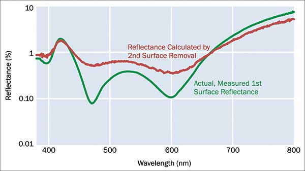
Alternately, some instrument makers don’t suppress the second surface reflection, but instead use a mathematical algorithm to subtract it from the measured data. Unfortunately, this approach requires assumptions be made about the refractive index and absorption characteristics of the glass under test that can’t easily be verified. This substantially limits results accuracy. (See Figure 3.)

Figure 3. Mathematically removing the second surface reflectance doesn’t provide accurate results. Photo courtesy of Gamma Scientific.
A more ideal solution is to introduce some sort of spatial filtering into the collection optics. This takes advantage of the fact that at other than normal incidence there is a lateral displacement between the desired top surface reflection and the other multiple reflections. This approach delivers superior accuracy, especially for antireflection coatings, and doesn’t increase measurement cost. And, importantly, this method can be successfully applied with glass substrates having thicknesses as low as 0.5 mm. This is critical because thin glass is being used increasingly in displays.
The other significant limitation of many spectrophotometers is that they are designed for laboratory use, rather than in-line production environments. Typically, they can only measure a small (usually 2-inch-square) witness sample, which must be manually placed inside the instrument. Furthermore, their measurement speed is not sufficient to keep pace with many production processes.
Gamma Scientific has developed a new range of products that are the first to address all these shortcomings simultaneously, making them suitable for a variety of industrial inspection applications. Specifically, these spectrophotometers all
incorporate spatial filtering to suppress second surface reflectance to deliver highly accurate measurements. And, their measurement speed has been reduced from seconds down to milliseconds through the use of a back thinned CCD sensor, which offers increased sensitivity and shorter exposure times, and by the use of a highly efficient optical design.
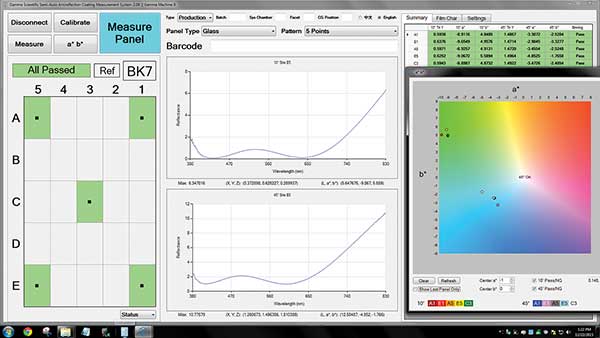
Also, these instruments are designed to test substrates of essentially any size, and can be configured with motion control and part handling hardware to support fully automated operation. In addition, they offer a flexible software interface that can display anything from detailed measurement data to simple go/no go results for easy interpretation by production line personnel. (See Figure 4.)

Figure 4. Instrument displays can be configured to provide detailed measurement data in tabular or graphical format, or simply a go/no go assessment. Photo courtesy of Gamma Scientific.
Grading Glass
There are currently two different methods for coating architectural glass. In the pyrolytic process, the glass is coated as it emerges from the float glass furnace in the form of a long ribbon. In the second approach, the glass is first cooled and cut, and the individual pieces are coated using magnetron sputtering. But, in both cases, the glass continuously rolls by under the coating equipment. And, for both processes, substrates are typically several feet wide.
For in-line glass measurement systems, the optical heads are mounted vertically, facing down. Product motion along the conveyor belt allows sequential sampling at multiple points along the length of the glass. Measurement at several points across the width of the glass is enabled by placing a single optical head on a laterally moving, motorized gantry, or by having multiple, fixed optical heads. (Typically, glass manufacturers want to measure three to five different points along the width of the glass.)
Since the product under test is physically large, it can’t easily be moved vertically. So the optical head(s) move on a vertical motorized stage to maintain the correct measurement distance as the glass travels by.
System software can be configured to give the same kind of pass/fail or detailed readouts as described previously. But, for pyrolytic coating production lines, the ability to perform high-speed, in-line testing also enables the color measurement system to be used as a real-time process control tool. Specifically, measurement results can be continuously fed back to adjust coating and other manufacturing parameters as needed to maintain the process before it wanders out of specification. This minimizes scrap and can significantly lower production costs. Also, the system can be used to bin products, that is, sort them into groups that have essentially indistinguishable appearance, rather than scrapping parts.
In conclusion, the applications for thin-film coatings have diversified as manufacturers of consumer and commercial products seek to deliver goods with ever-greater functionality and improved performance. But the emphasis on cosmetic coating appearance in these applications requires inspection methods that correlate quantitatively with human vision. To meet this need, instrument builders are creating a new generation of tools that offer higher performance, increased speed and easier integration into existing production lines.
Meet the author
Trevor Vogt is technical product manager at Gamma Scientific; email [email protected], www.gamma-sci.com.