Spectral imaging has grown from an expensive research-oriented technique to one that is applicable for a wide range of scientific and industrial applications. This article looks at real-life systems, the arrangement of the instrumentation and examples in process control and monitoring.
Dr. John R. Gilchrist, Clyde HSI; Timo Hyvärinen, Spectral Imaging Ltd.
Hyperspectral imaging spectroscopy has developed dramatically from a large, complex, remote-sensing satellite- or aircraft-based system into a rugged, compact, economically priced imaging and spectroscopic tool for a range of process control, monitoring, diagnostic and inspection applications. Applications include colorimetry and color matching, spectral radiometry, industrial process control and quality assurance, pharmaceuticals preparation and packaging, forensic analysis, bio-agents detection, camouflage detection, live cell microscopy, genomics and proteomics research and precancerous cell detection in the life sciences.
The use of imaging techniques for scene evaluation has become a key method for nondestructive, remote evaluation. Conventional imaging, whether monochrome or color, depends upon the spatial resolution of the image. If the image is blurred or too fuzzy then the viewer cannot determine exactly where or what the object under view is. Hyperspectral imaging adds significant additional information to the brightness analysis of a scene by adding the light intensity as a function of wavelength, its spectrum, from each image’s spatial position. This additional spectral dimension can be rapidly and straightforwardly analyzed to provide an image-contrast capability that is not present in a normal scene-brightness approach.
In the early 1970s, the remote sensing satellite, LandSat I, was the first to provide multispectral images of the Earth's surface using reflectance spectroscopy. Today, compact imaging spectrograph systems are available that provide significantly more spectral information than the original LandSat system and that also can be easily handheld.
Some confusion
There is confusion over the precise definition of multispectral, hyperspectral, ultraspectral or full-spectral imaging and the detection capability of each system. Table 1 presents a definition of these instrument modes. As we will show, the range of a spectral imaging system depends on instrument design from the front-end collection optics to the back-end detection system, as well as the imaging spectrograph design and operating parameters.
TABLE 1.
DEFINITIONS OF IMAGING MODES
|
Mode
|
|
Number of
Spectral Bands |
|
Spectral Resolution
|
|
Capability
|
|
Availability |
| |
Imaging |
|
None |
|
None, sensitivity depends on detector spectral response |
|
Image brightness |
|
Now |
| |
|
|
|
|
|
|
|
|
|
| |
Multispectral |
|
Few to tens |
|
Medium, many
tens of nm |
|
Detects solids and liquids |
|
Now |
| |
|
|
|
|
|
|
|
|
|
| |
Hyperspectral |
|
Hundreds to ~thousands |
|
Narrow, few nm |
|
Detects and identifies solids and liquids |
|
Now |
| |
|
|
|
|
|
|
|
|
|
| |
Ultraspectral |
|
Thousands |
|
Very narrow |
|
Detects and identifies solids, liquids and gases |
|
Emerging technology but very expensive and processor hungry |
| |
|
|
|
|
|
|
|
|
|
| |
Full spectrum |
|
Thousands to "continuous spectra" over full optical spectral range from UV to IR |
|
Very narrow |
|
Detects and identifies solids, liquids and gases |
|
Proposed technology and data processing system |
Of course, scene illumination is important to successful spectral imaging and care should be taken to correctly evaluate the optical budget under specific spectral, spatial and signal integration conditions to ensure that the system’s signal-to-noise ratio is appropriate for the measurement precision required by the application. This is an often-overlooked issue and is one of the main reasons for measurement performance being compromised. Simply said, if one cannot get any light or enough light into the imaging spectrometer, it doesn't matter how good the system is spectrally, spatially or otherwise; it will not measure what is required by the user.
To be considered a hyperspectral imager, an instrument needs to make simultaneous or near-simultaneous spectral measurements from a series of continuous spatial positions. The key information contained in these measurements is the shape and features of the spectral curve, not necessarily the absolute radiances that are measured, at each spatial position. The more spectral features that are available, the higher the potential information about the sample that can be extracted. Thus to achieve this goal, it is desirable to maximize the spectral resolution and coverage to a point where no more features are present.
Hyperspectral data sometimes is treated as extended multispectral data with lots of additional bands — a practice which is generally counterproductive and a waste of bandwidth and analysis time. Techniques are available to fit curves to the spectral data and hence provide key information about the samples. The quality of the acquired information depends upon the instrument performance characteristics, the illumination conditions and the analysis of the measured data — all of which are often determined from the specific requirements of an application.
Spectral imaging tools
The optical and spectral characteristics of a hyperspectral imaging system are determined largely by the application requirements. However, all systems have the same basic components in common: a means to image the object, a means to provide both spectral and spatial resolution, and a means of detection. This paper focuses on imaging spectrograph design and the associated two-dimensional array detector for spectral image capture.
The classic, though inefficient, method to make spectral images has been to sequentially take the same “photograph” through a series of wavelength bandpass filters and construct an image spectral cube data set — X-position vs. Y-position vs. wavelength. Traditional methods of wavelength selection have used dielectric optical bandpass filters but the use of either an acousto-optic tunable filter (AOTF) or a liquid crystal tunable filter have permitted electronic sweeping of the spectral bandpass.
In each of these cases, an image is collected one wavelength after the other and the field of view (FOV) of the imaging system is fixed. Filter-based methods place a huge burden on the sample and illumination stability as well as being a time- and computation-intensive process. In the minimum experiment, it is necessary to wait until all wavelength images have been recorded, which may take from minutes to hours of measurement time depending upon samples, illumination and integration conditions. Therefore, if an object is moving or is spectrally unstable due to its chemical, physical or physiological characteristics, then the integrity of the resulting hyperspectral data cube may be seriously in question.
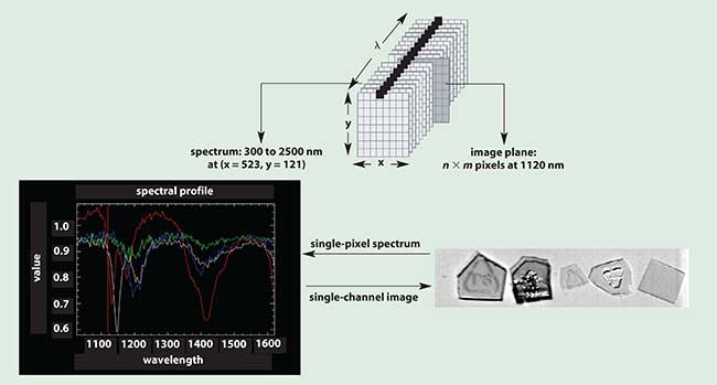
Figure 1. The hyperspectral data cube and its relationship between spatial and spectral dimensions.
True spectral imaging requires all of the wavelengths to be recorded simultaneously — that is, a wavelength-dispersive system is required. In this case, the FOV is generated sequentially and the hyperspectral integrity of the data is maintained for each and every measurement, even if the sample dynamics are changing or if the sample is moving. An image of the FOV is collected by translating the sample across the slit aperture of the spectrograph in a method known as pushbroom acquisition. Thus the wavelength or spectral data are measured simultaneously and the image or FOV is generated sequentially. There is essentially no delay in acquisition which guarantees the integrity of spectral data and ratios. The spectral image builds up in real time and can be stopped at any time. This means that spectral snapshots are possible without the need to take the full image field of view. Figure 1 shows the arrangement of the spectral hypercubes. In principle, the data collected in either the filter or pushbroom approach are complementary to each other in terms of the basic concept.
Optical arrangement
The complete optical system for a hyperspectral imaging system consists of a suitable objective lens matched to the spatial and spectral requirements of the application, the imaging spectrograph proper and a two-dimensional detector to simultaneously collect the spectral vs. spatial information.
Figure 2 illustrates the general arrangement of the ImSpector system. The objective lens images the target onto the slit of the main element of the spectral camera: the transmission grating spectrograph. The slit, grating and detector characteristics determine the spectral resolution. The spatial resolution is determined by the pixel size of the two-dimensional camera and the objective lens as the spectrograph is designed with a magnification of 1. The transmission-grating approach offers a compact, robust and economical means to provide the required wavelength dispersion and also provides excellent spatial resolution.
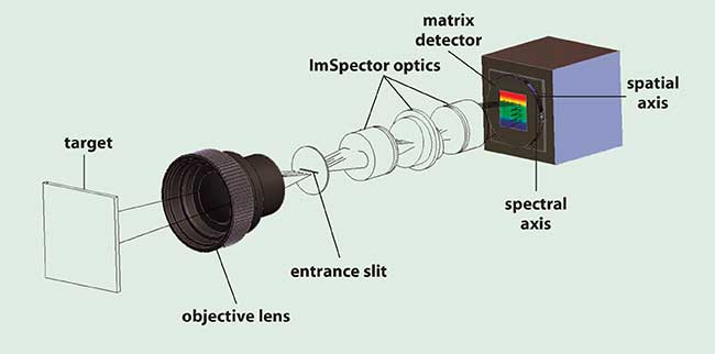
Figure 2. Optical arrangement of the hyperspectral imaging camera.
In general, such spectrographs offer excellent optical and dispersive efficiency, up to 80 percent, and almost no polarization dependence. This contrasts with other spectrographs based on reflective gratings in either an asymmetric Czerny-Turner (CT) or Offner design. Alignment, wavefront flatness and device stability are critical in such spectrographs, although designs are available that offer excellent imaging performance, though in a larger physical package than the ImSpector-type design. Because CT and Offner designs use reflection gratings, the polarization dependences can also be strong. This may cause issues of spectrograph efficiency in, for example, fluorescence and biophysical applications, where the anisotropy of a sample is one of the key measurements to understanding cell/drug interactions.
Typical imaging quality of the transmission grating spectrograph performance is excellent, with subpixel smile and keystone. This means that the spatial and spectral image quality across the output field of the spectrograph is essentially the same at all points on the detector, ensuring the capability for high spectral resolution and purity. In addition, the light throughput of the ImSpector provides typical spectrograph input f number of f/2, which provides a light-gathering capability four times better than an equivalent reflection spectrograph at f/4. Unfortunately, reflection-grating spectrographs may also suffer from a nonflat image field, distortion of the imaged point spread function across the field, and hence a compromise in spectral resolution and imaging performance may need to be made.
The two-dimensional detector for the spectrograph plays an important role in recording the spectral/spatial signal, and a variety of CMOS, CCD, InGaAs or MCT detectors can be used depending upon the requirements. Such cameras are available with a variety of interfaces such as C- and U-mounts to connect to the spectrograph, and USB2.0, FireWire, CameraLink, Ethernet and LVDS to connect to the computer. The use of screw mounts to connect the camera to the spectrograph are preferred over bayonet mounts due to increased stability of the mount.
For many industrial applications, a CCD or CMOS camera with 12-bit dynamic ranges is adequate and can provide high frame rates. For more demanding scientific applications, such as cell, fluorescence or Raman imaging, a higher performance 16-bit cooled camera may be advantageous. A useful review on how to choose a scientific grade CCD camera is given in Photonics Spectra, March 2002.
No spectral imaging system would be complete without the use of data analysis software to extract from the hyperspectral data the key information about the process or samples being monitored. A typical work flow is described in Figure 3.
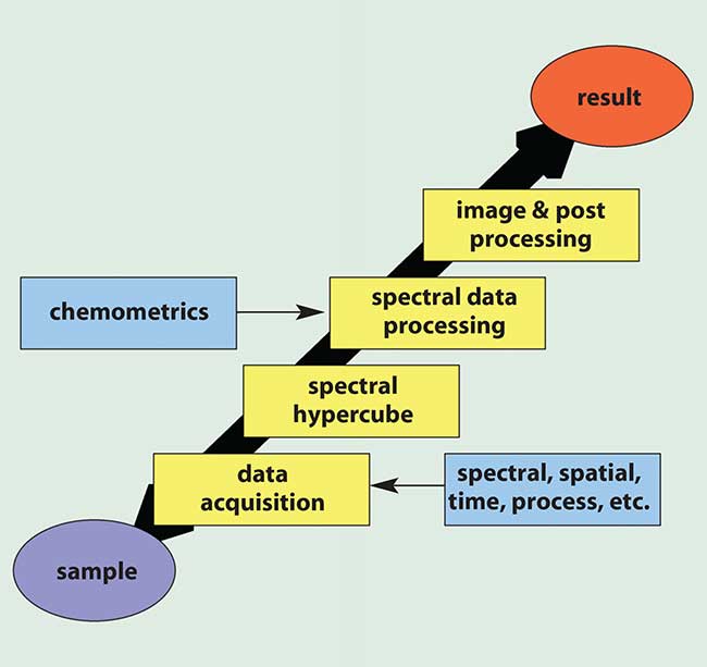
Figure 3. Spectral imaging work flow.
In any system, a clear understanding of the application’s requirements for the system, the illumination conditions and the signal processing work flow are required. Such an end-to-end approach to the instrument hardware and software design seeks to analyze the individual components’ performance so as to eliminate any performance bottlenecks. The key to good performance is simplicity and stability.
Some examples
Hyperspectral imaging has been successfully applied to a number of process control, monitoring, inspection and scientific applications. The most well-known application is in remote sensing of the Earth using either air- or satellite-borne systems. Such monitoring has been used to study agricultural effects, monitor the distributions of phytoplankton and chlorophyll-a in lakes, and detect and map invasive species in wetlands, swamps and prairies.
In the industrial process monitoring and control area, hyperspectral imaging is becoming a more important diagnostic tool; examples are found in areas from paper processing, dye colorimetry, LCD panel testing, and pharmaceutical manufacturing and quality control.
In the paper processing environment, the water content of the paper is a critical parameter that determines the amount of drying power required and also the speed of paper production. Figure 4 shows the process environment and the results from the spectral imaging measurement as used by Metso Automation in Finland. The paper is transported at high speed through the process. A near-infrared spectral imaging system monitors 100 spatial positions across the width of the paper web and, in real-time, measures, analyzes and reports the moisture content of the paper. This allows the plant control system to automatically adjust its operating conditions for optimum throughput of production and uniform quality of paper.
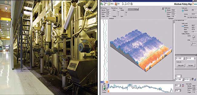
Figure 4. Moisture content monitoring for a paper process as used by Metso Automation.
Such measurements are not only very cost effective in the general operation of the plant but also in the start-up period from service points. Typically, the process is stabilized after about 30 to 60 minutes of operation; however, with a hyperspectral imager providing real-time moisture content, this time is reduced to just a few minutes. This saves tons of paper and reduces manufacturing costs.
In the US, the Food and Drug Administration has released new guidelines which advocate the use and development of measurement techniques in pharmaceutical manufacturing: the Process Analytical Technology (PAT) initiative, as it is known, promotes the monitoring of process-critical parameters in manufacturing such as the composition, strength, quality and purity as well as homogeneity of powder blends and tablets. This is of critical importance during the manufacturing process and also in the final product to ensure correct drug formulation, quality of drug release and its effectiveness.
NIR and Raman spectroscopy along with conventional chemical analysis such as HPLC has been used to analyze individual samples off-line, which is time and resource consuming. Hyperspectral imaging has been used online to perform blend uniformity and tablet variability analysis. In addition, it has also been used for package monitoring to ensure that the correct tablets are placed in the correct package, detect incorrect products, identify broken tablets or detect empty slots in the package.
Package measurements employ NIR hyperspectral imaging and diffuse reflectance. Figure 5 demonstrates the results from a conventional visible image of a blister pack containing a rogue tablet, and the NIR hyperspectral image of the same pack. The additional information content of the spectral image clearly identifies the rogue tablet and the pack can then be automatically rejected for further determination of the issue.
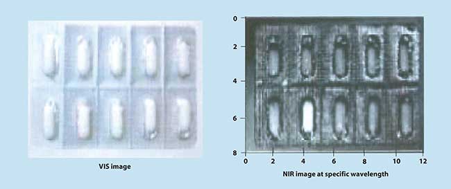
Figure 5. Pharmaceutical process control and blister pack inspection.
Large flat panel TFT displays for computer and consumer use are gaining popularity as manufacturing costs drop. The reproducibility and color quality of these displays is of utmost importance, especially considering the cost of rejecting a large panel. An adaptation of hyperspectral imaging has been used to simultaneously monitor up to 100 spatial positions in a two-dimensional spatial matrix for panel testing. The optical fiber assembly converts the 2-D matrix into a line to match the spectrograph input slit. Figure 6 shows the testing arrangement and the realization of a 100-fiber spectral imaging camera for TFT panel testing.
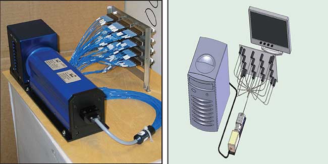
Figure 6. TFT panel testing using fiber optic sampling and spectral imaging camera.
The wealth of additional information available and the application benefits that hyperspectral imaging produce are almost without limit. Since its early use in satellite remote sensing, both the technique and optical instrumentation have developed to support applications that require real-time process monitoring, control, inspection, quantification and identifications. The use of transmission-grating imaging spectrographs has allowed these systems to be compact and robust and to possess excellent spatial and spectral performances at a cost level not easily matched by comparable instrumentation. It can be expected that the growth in hyperspectral imaging will continue in chemical monitoring, whether it is the life sciences, forensics, homeland security, pharmaceuticals or any other application where the spectral information provides a dramatic contrast improvement in sample conditions and features compared with conventional imaging systems.