Full company details
Teledyne Princeton Instruments
Bus. Unit of Teledyne Technologies
 3660 Quakerbridge Rd.
Trenton, NJ 08619
United States
Phone: +1 609-587-9797
Toll-free: +1 877-474-2286
Camera Optimization Helps to Clarify In Vivo Diagnosis and Plan Treatment
BioPhotonics
Sep/Oct 2021Increased detector sensitivity, optimal spatial resolution, and reduced cumulative noise are key factors for enhancing image quality to enable well-informed medical decisions.EMMA MCCARTHY, TELEDYNE PRINCETON INSTRUMENTS
Pre-clinical in vivo studies are essential to our understanding of human disease, as well as to the development and administration of new treatments and therapeutic agents. Noninvasive, pre-
clinical, in vivo imaging techniques allow for long-term studies of treatments. To that end, advanced optical imaging, made available by modern camera technology, can be used to deliver fast, accurate, real-time quantitative measurements.
Optical imaging technology takes advantage of the fact that different biological tissues scatter light at varying degrees. Through scattering, a researcher or clinician can observe biological functions, such as a change in metabolism or any changes in physiological effects. Figure 1 shows an example of in vivo optical imaging. Although the technique does not directly translate to the clinic, it is an essential resource for pre-clinical imaging
1.
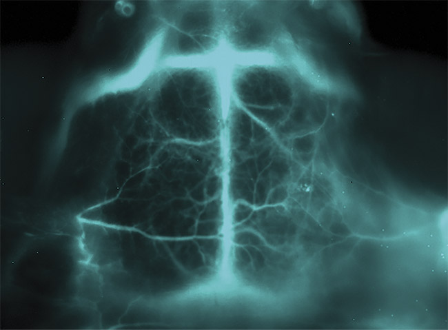
Figure 1. An in vivo optical image of a middle cerebral artery occlusion within a mouse brain, taken using a NIRvana640 InGaAs camera from Teledyne Princeton Instruments and a 1350-nm longpass filter. Courtesy of Artemis Intelligent Imaging.
The two most useful optical imaging techniques for in vivo analysis are fluorescence and bioluminescence imaging. Fluorescence imaging relies on the excitation of a fluorescent probe at one wavelength and emitting a different (usually longer) wavelength for detection
2. Bioluminescence imaging is the result of an enzymatic reaction in which light-emitting proteins that are naturally occurring are used to target the biological molecule of interest
3.
These two techniques have advanced as a result of enhancements in camera equipment, processing power, and data storage capacity. However, because specific wavelengths scatter within biological tissues differently, deep penetration into tissues remains challenging for visible light imaging
1. Longer wavelengths, such as near-infrared (NIR) light, are able to penetrate deeper into the tissue, but they require different camera technology to capture the spectral data than visible light requires.
Choosing the right wavelength
Because fluorophores used in fluorescent optical imaging emit specific wavelengths, it is important to choose a fluorophore that offers the best imaging for the biological tissue of interest. For example, both ultraviolet and far-infrared light cause tissue trauma.
Although the majority of fluorescent probes emit within the visible range (400 to 700 nm), they are limited when imaging in vivo. Certain biological components, such as hemoglobin and water, absorb and scatter visible light, reducing tissue transparency. Furthermore, tissue autofluorescence occurs within the visible range, producing artifacts that influence imaging acquisition and any quantitative measurements
4.
NIR light, covering 700 to 1700 nm, is absorbed less by biological tissue, reducing scattering and autofluorescence. This means that biological components targeted by NIR fluorophores can be imaged at much deeper penetration depths. The two biological NIR windows are NIR-I (700 to 900 nm) and NIR-II (1000 to 1700 nm). Both windows allow for deeper penetration into biological tissue; however, the penetration depth of the NIR-I window is limited because autofluorescence is still prevalent
4.
The NIR-II window can be used to penetrate deeper into biological tissue, with increased image quality, allowing features such as blood vessels to be imaged noninvasively, as shown in Figure 2. However, NIR-II fluorophores are still in the early stages of development and are not readily available for in vivo studies
4.
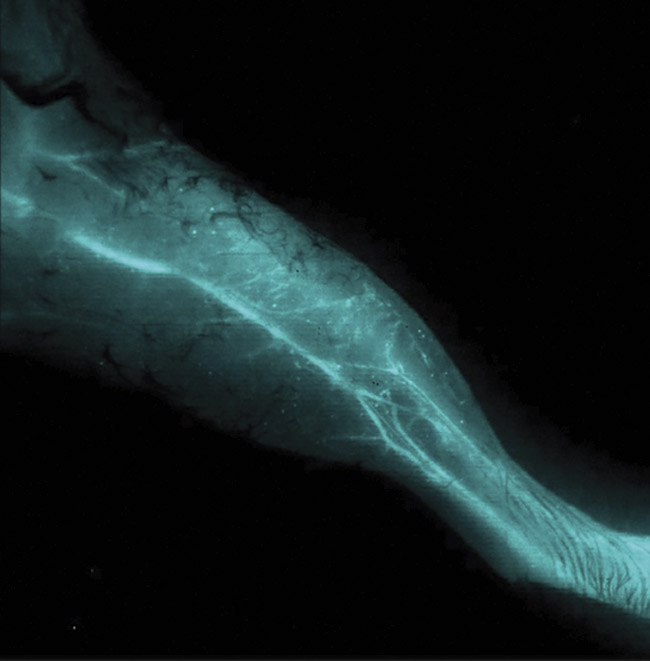
Figure 2. A noninvasive, NIR-II optical in vivo image of the vascular structure within a mouse leg. Image acquired using a NIRvana640 InGaAs camera. Courtesy of Artemis Intelligent Imaging.
NIR-I wavelengths can be detected by silicon-based cameras, which are typically used for visible imaging. NIR-II wavelengths, however, cannot be detected by silicon-based cameras, and instead require indium gallium arsenide (InGaAs) cameras. These two camera types have different sensor characteristics and therefore need to be optimized for either NIR-I or NIR-II optical imaging.
Increased image quality
Most high-performance, in vivo imaging systems use either a charge-coupled device (CCD) for imaging in the visible-to-NIR-I range or an InGaAs detector for NIR-II imaging. Regardless of sensor technology, three main camera parameters determine the quality of image acquisition: detector sensitivity, spatial resolution, and cumulative noise.
Detector sensitivity is determined by pixel size, as well as the number of photons the camera is able to convert into electrons to produce a digital image. This is called quantum efficiency. Spatial resolution is determined by the sensor architecture, including pixel size and total number of pixels. Cumulative noise is the combined contribution of a camera’s read noise, dark current noise, and any additional noise sources.
Camera quantum efficiency
The quantum efficiency of a camera is influenced by how well its sensor is able to convert photons to electrons, combined with the transmission rate of its optics and filters. This is typically expressed as a percentage of the signal collected by the system.
Different camera technologies have different wavelength sensitivities, which is why CCD cameras are optimized for visible wavelengths and InGaAs cameras are optimized for NIR-II wavelengths. To further increase quantum efficiency, CCD sensors can be back-thinned. This means that photons interact with the sensor first, without risk of being absorbed by any surrounding electronics. This allows back-thinned CCD sensors to have peak quantum efficiencies of >95%, which is more than 15% higher than traditional front-illuminated CCD sensors.
Deep-depleted CCD cameras provide the best sensitivity for NIR-I wavelengths due to the cameras’ thicker depletion region, which enables sensing beyond the visible range. Traditional cameras are unable to detect NIR-I wavelengths because the longer the wavelength, the deeper within the silicon structure the photons travel before generating a signal charge. However, by using thicker silicon (deep-depleted) sensors, NIR wavelengths can be detected
5. Figure 3 shows the quantum efficiency of various sensors.
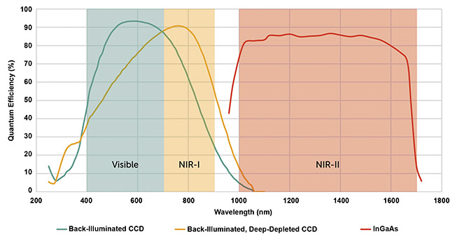
Figure 3. The quantum efficiency of optical imaging in vivo cameras. A typical back-illuminated CCD camera (green line), a back-illuminated, deep-depleted CCD camera (yellow line), and an InGaAs camera (red line), alongside the corresponding wavelength sensitivity. Courtesy of Teledyne Princeton Instruments.
Influences on spatial resolution
Although wavelength, sample, and signal intensity play significant roles in image resolution, it is also important that the chosen camera has the right sensor characteristics to optimize spatial resolution (in other words, the smallest object that can be resolved). The physical size of a sensor and the optics of the camera establish the limits of the field of view and the total signal collected from the sample. These parameters vary for different camera types, with CCD-based cameras typically having larger options for total sensor area than InGaAs cameras.
The number of pixels and their size is also a consideration. Smaller pixels offer higher resolution, but at the expense of collecting less signal for a given noise. To overcome this, the signal from multiple pixels can be cumulatively added via a process called pixel binning. This process increases the sensitivity but decreases resolution in the process. This may be useful to a researcher or clinician who is studying in vivo drug localization. If the localization is deep within the body, the fluorescent signal will typically be weak. This means that sensitivity is the most important factor in capturing as much of the faint signal as possible.
By choosing a camera with the appropriate sensor area, pixel number, pixel size, and camera optics, the optimal spatial resolution can be obtained for an in vivo study.
Reducing noise via deep cooling
Signals produced during in vivo imaging are extremely faint and therefore rely on highly sensitive cameras. Reducing cumulative noise is one of the ways in which the sensitivity of the camera can be increased. One of the common noise sources within in vivo imaging is thermally generated noise, known as dark current noise, which is determined by the dark current (the result of thermally generated electrons) and the total exposure time. Therefore, dark current noise increases over the longer exposure times that are typical within in vivo studies.
Luckily, dark current noise can be drastically reduced via deep cooling, allowing integration times of up to multiple hours. A number of different cooling technologies are available for reducing the thermal noise. Thermoelectric, or Peltier, cooling is the most attractive option because it is maintenance-free and reliable. However, to ensure the deepest level of cooling (between −60 and −100 °C), multiple requirements must be met, including an ultrahigh vacuum environment around the sensor (Figure 4a) and the use of non-outgassing materials and a permanent, all-metal hermetic seal. Although epoxies can be used, they are unable to ensure the deepest level of cooling.
InGaAs cameras suffer from dark current noise more than CCD cameras do because of the low bandgap of InGaAs material, so it is essential that InGaAs cameras are deeply cooled. For ultralow-light in vivo imaging, it is sometimes necessary to use liquid nitrogen to deeply cool the camera down to −190 °C. Figure 4b shows that drastically deep cooling an InGaAs camera can reduce the dark current. In addition, InGaAs cameras are affected by ambient background radiation, so both the sensor and the optical path need to be cooled to minimize noise contributions.
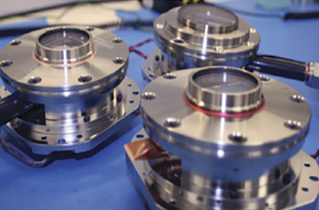
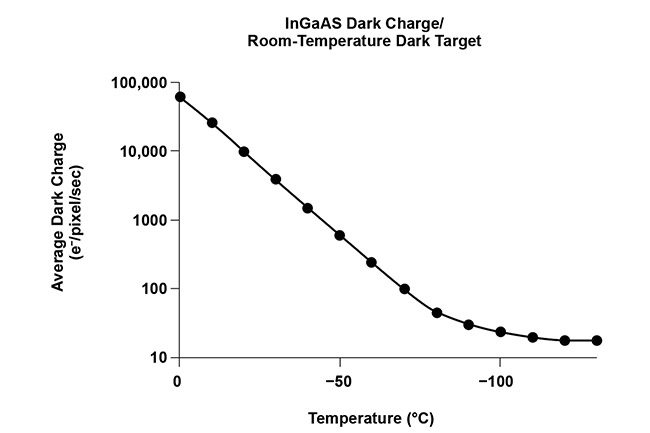
Figure 4. A typical high-performance vacuum assembly, which is essential for the deep cooling of cameras used for in vivo imaging (top). The relationship between the dark current (and therefore dark current noise) and temperature of an InGaAs camera, showing that deep cooling an InGaAs camera drastically reduces the amount of dark noise (bottom). Courtesy of Teledyne Princeton Instruments.
Another source is the readout noise that is generated by the camera electronics, which amounts to the accumulation of all the noise produced by each component that is required to convert the charge into a pixel. Although unavoidable, readout noise can be reduced by slowing the rate at which the charge collected is converted into a signal. Deep cooling of a camera will minimize transfer rate, reducing the overall readout noise.
In vivo optical imaging is an essential resource for understanding disease development and the effectiveness of treatment. Although visible light is the most common wavelength used within optical in vivo imaging, it has limitations. The NIR-I and NIR-II wavelengths offer increased depth penetration and improved image resolution.
NIR-I and NIR-II wavelengths require different camera types in order to be detected. The NIR-I window requires deep-depleted CCD cameras and the NIR-II requires InGaAs cameras. Although these cameras use different sensor materials and architectures, certain camera parameters must be optimized for both sensor types.
Detector sensitivity, spatial resolution, and cumulative noise sources must be evaluated to ensure high-quality in vivo imaging. Choosing a camera with the highest sensitivity for the wavelength range of interest is essential and will ensure that the maximum number of photons are being converted into electrons and therefore signal. Although spatial resolution depends on the sample type, the wavelength used, and the signal intensity, sensor parameters, such as pixel size and sensor area, are also important.
Advancements in camera technology — from minimizing dark current noise by creating reliable camera cooling to optimizing image sensitivity and resolution via pixel size — have improved the image quality of preclinical in vivo fluorescent imaging.
The most effective technological advancement for cameras has been the improvement of InGaAs sensor technology. Alongside the development of NIR-II probes, the improvements have enabled the imaging penetration depth of tissue to increase from a few millimeters to beyond 2 cm. This means that deep biological processes, such as the movement of drugs through the digestive tract, can be imaged completely noninvasively, providing vital information about drug control and release that couldn’t be measured before.
Meet the author
Emma McCarthy, Ph.D., is a marketing manager at Teledyne Princeton Instruments. She has an educational background in physics and biochemical engineering from the University of Warwick and the University of Birmingham, both in England. Her doctorate focused on various techniques to evaluate the influence of external factors on the physical and chemical response of biomolecules; email:
[email protected].
References
1. J.P. Roberts (February 2020). Recent developments in small animal imaging.
Biocompare,
www.biocompare.com/editorial-articles/560606-recent-developments-in-small-animal-imaging/.
2. A.J. Studwell and D.N. Kotton (2011). A shift from cell cultures to creatures: in vivo imaging of small animals in experimental regenerative medicine.
Mol Ther, Vol. 19, Issue 11, pp. 1933-1941,
www.doi.org/10.1038/mt.2011.194.
3. S. Yanping and N.B. Herbert (2016). Neuroimaging of brain tumors in animal models of central nervous system cancer. In
Handbook of Neuro-Oncology Neuroimaging,
2nd ed. H.B. Newton, ed. Academic Press,
pp. 395-408.
4. J. Zhao et al. (2018). NIR-I-to-NIR-II fluorescence nanomaterials for biomedical imaging and cancer therapy. J Mater Chem B, Vol. 6, pp. 349-365,
www.doi.org/10.1039/c7tb02573d.
5. E.M. McCarthy (2020). Silicon-based CCDs: the basics. Teledyne Princeton Instruments,
www.princetoninstruments.com/learn/camera-fundamentals/ccd-the-basics.