With spatial correction, line scan polarization cameras detect birefringence, stress, surface roughness, and physical properties that cannot be detected with conventional imaging.
XING-FEI HE, TELEDYNE DALSA
There are three fundamental properties of light: intensity, wavelength, and polarization. Almost all cameras today are designed for monochrome or color imaging. A monochrome camera is used to measure the intensity of light over a broadband spectrum at pixel level1, while a color or multispectral camera is used to detect the intensities of light at the red, green, blue, and near-IR wavelength bands2,3. Similarly, a polarization camera captures the intensity of light at multiple polarization states.
According to a recent AIA market study, worldwide camera sales in machine vision reached $760 million in 2015, with about 80% from monochrome cameras and 20% from color cameras. While polarizers are commonly used in machine vision, until now there have not been line scan polarization cameras that capture images of multiple polarization states.
Polarization offers numerous benefits, not only detecting geometry and surface, but measuring physical properties that are not detectable using conventional imaging. In machine vision, it can be used to enhance contrast for objects that are difficult to distinguish otherwise. When combined with phase detection, polarization imaging is much more sensitive than conventional imaging.
Polarization filter technologies
Like human eyes, silicon cannot determine light polarization. Therefore, a polarization filter is required in front of the image sensor; the image sensor detects the intensity of light with the polarization state defined by the filter.
Most common types of polarization filters fall into one of three categories: division of time, division of amplitude, or division of focal plane (Table 1). For division of time polarimetry, data is acquired sequentially in time as a polarization element, such as a liquid crystal, polarizer, or a photoelastic modulator, is rotated or modulated. The speed is limited by the modulation. In many applications today, a high line rate of about 100 kHz is required; division of time filters have inherent limitations. Cost is also high due to complicated designs.

For division of amplitude filters, light is split into different optical paths, where each path has a separate sensor. A prism is the most commonly used component where accurate registration is often difficult to achieve. Also, the housing is usually large in order to accommodate the prism.
For division of focal plane filters, a micro-polarizer array is placed on the focal plane to define different polarization states. The technology is suitable for compact, robust, and low-cost designs. However, for area scan imagers there are inherent disadvantages in spatial resolution as each pixel only provides data for one native polarization state. Algorithms are used to interpolate others.
Line scan polarization cameras using micropolarizer filters overcome the shortcomings mentioned above. In line scan, multiple arrays with different polarization filter orientations capture images simultaneously but at slightly different positions. Spatial correction allows the camera to align all channels at the same object point. The advantage of line scan over area scan is that it provides multiple native polarization state data without any digital manipulation.
Sensor architecture
One available polarization camera (Figure 1) incorporates a CMOS sensor with a quadlinear architecture. A micropolarizer array consisting of nanowires is placed on top of the silicon; the nanowires have a pitch of 140 nm and a width of 70 nm, while the orientation of the micropolarizer filters is 0°, 135°, and 90°, respectively, on the first three linear arrays. The intensity of the filtered light is recorded by the underlying arrays. The fourth channel is an unfiltered array, which captures the total intensity, equivalent to a conventional image, while the gaps in between the active arrays reduce spatial crosstalk.
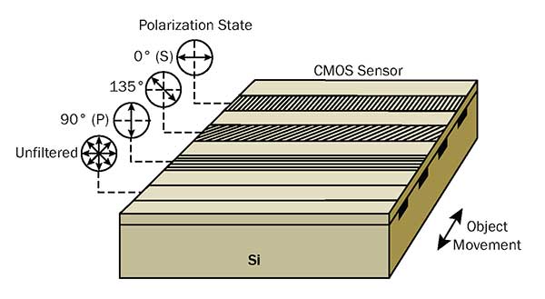
Figure 1. Schematic of polarization camera is sensor architecture. The nanowire micropolarizer filters are placed on top of silicon (Si), which define 0° (s), 135°, and 90° (p) polarization states, respectively, on the first three linear arrays. The fourth array is an unfiltered channel that records a conventional unfiltered image. Courtesy of Teledyne Dalsa.
Light is an electromagnetic wave. Its electrical field, magnetic field, and propagation direction are orthogonal to one another. Polarization direction is defined as the electrical field direction. Light, with its electrical field oscillating perpendicular to the nanowires, passes through the filter while that in the parallel direction is rejected. When the line scan camera is mounted at an angle to the web in a reflection configuration, the 0° channel transmits s-polarized light (polarization perpendicular to the plane of incidence) while the 90° channel transmits p-polarized light (polarization parallel to the plane of incidence). Assuming the camera outputs I0, I90, I135, and Iuf, from 0°, 90°, 135° polarization and unfiltered channel, respectively, the intensity of s-polarized and p-polarized states are:
Is = I0
Ip = I90
The key differentiation between line scan and area scan using micropolarizer filters is the number of native polarization state data per pixel. An area scan imager generally uses 0°, 45°, 90°, and 135° polarization filters arranged in a so-called super-pixel format4, where each pixel captures one native polarization state. Interpolation algorithms are then used to calculate the three other states based on the information from neighboring pixels. This results in poor data accuracy because of the loss of spatial resolution. For line scan cameras, on the other hand, each polarization state has 100% sampling. Multiple native polarization state data are physically measured. The contrast ratio of the nanowire micropolarizer filters are shown in Figure 2.
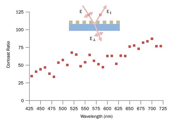 Figure 2. Contrast ratio of nanowire-based micropolarizer filters. Courtesy of Teledyne Dalsa.
A contrast ratio of 30~90 is observed depending on wavelength. Higher contrast ratio can be realized with future designs.
Stokes parameters, S0, S1, S2, etc., are often used to analyze physical properties of materials. Differential polarization, degree of linear polarization (DoLP) and angle of polarization (AoP) are all useful parameters.
Image visualization
Polarization images are largely uncorrelated to conventional images based on intensity. In a vision system, data processing could be implemented in each specific polarization state or their combinations. It’s useful to have a representation of polarization images considering human’s inability to see it. Color-coded polarization images are probably the most popular as they not only give visual perception but also utilize the standard data structure and transfer protocols in color imaging.
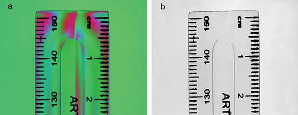
Figure 3. Color-coded polarization image (a) compared with a conventional, unfiltered image (b) of a plastic ruler captured by a polarization camera. In the polarization image, RGB represent 0°(s), 90°(p), and 135° polarization state, respectively. Courtesy of Teledyne Dalsa.
Figure 3 shows a color-coded polarization image of a plastic ruler captured by a polarization camera, where RGB represent 0° (s-polarized), 90° (p-polarized), and 135° polarization state, respectively. A conventional image captured by the unfiltered channel is also compared. Obviously, the polarization imaging reveals built-up stress inside the plastic ruler that cannot be detected by conventional imaging.
Detectability
The machine vision industry is facing many challenges in detectability as speed reaches to about a 100-kHz line rate and object resolution shrinks to submicron. Different technologies have been developed, such as time delay integration to improve signal-to-noise ratio, and color
and multispectral imaging to obtain spectral characteristics. However, higher contrast is required based on the physical properties of materials. Polarization plays a key role here as it is very sensitive to any change on the surface or interface. Because of phase detection, polarization-based imaging is much more sensitive than intensity-based imaging.
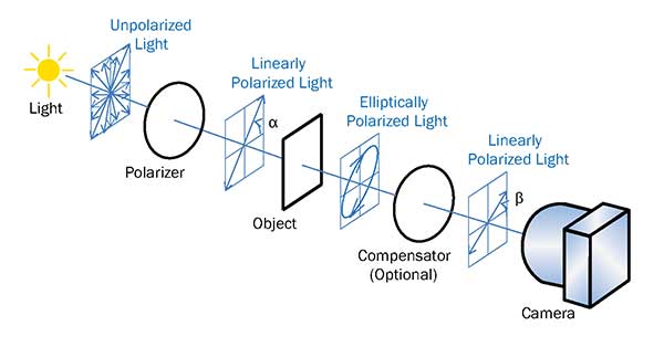
Figure 4. Transmission configuration: A polarizer converts the light source into linearly polarized light. When the linearly polarized light transmits through the object, it generally becomes elliptically polarized due to birefringence. An optional compensator, e.g., λ/4 plate, can be used. Finally the image is captured by the polarization camera. Courtesy of Teledyne Dalsa.
A transmission configuration (Figure 4) is commonly used for transparent materials such as glasses and films. Generally, a polarizer is used to convert the light source into linearly polarized light. When the linearly polarized light passes through the object, it generally becomes elliptically polarized due to birefringence of the object. An optional compensator such as a λ/4 plate could also be used in the optical path. Finally the image is captured by the polarization camera. The angles of polarizer and compensator can be adjusted for optimum performance.
A reflection configuration (Figure 5) is used for opaque materials. Reflected light from many materials such as semiconductors and metals are polarization-dependent.
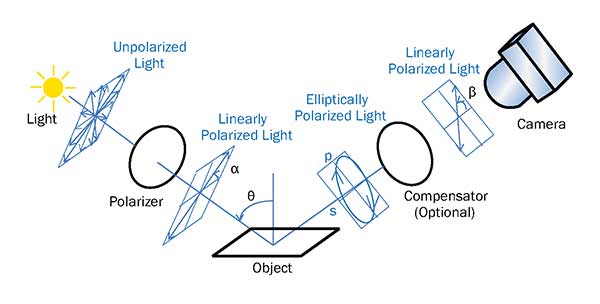 Figure 5. Reflection configuration: A polarizer converts the light source into linearly polarized light. When the linearly polarized light is reflected from the object, the reflected light generally becomes elliptically polarized. Rotate the angles of polarizer and compensator for optimal performance. Courtesy of Teledyne Dalsa.
A polarizer converts the light source into linearly polarized light. When the linearly polarized light is reflected from the object, the reflected light generally becomes elliptically polarized. By rotating the angles of polarizer and compensator, one can achieve a linearly polarized light that reaches the camera. The configuration is similar to ellipsometry5. The difference is that rather than using a rotating analyzer, the camera captures different polarization states, simultaneously, with lateral spatial resolution. Light is a linear light source rather than point source.
In either of the configurations, when the physical property of the object changes due to defects, for example, the change alters the polarization state differently from the rest of the object. This change is then detected by the polarization camera with high sensitivity.
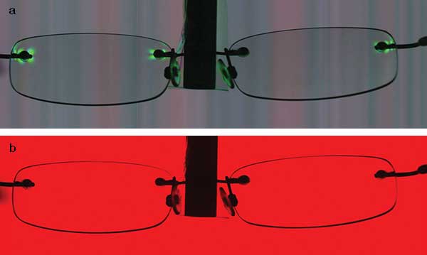
Figure 6. Polarization image (a) compared with a conventional, unfiltered image (b) of a pair of glasses. Stress surrounding the screws shows up in the polarization image while it could not be seen in the conventional image. Courtesy of Stemmer Imaging.
Mechanical force results in birefringence that changes the polarization state of transmitted light, as can be seen in the screws inducing stress on a pair of glasses (Figure 6). As can be seen in the unfiltered channel, conventional imaging cannot detect such stress. Note the image of electronic circuitry that contains scratches on the surface (Figure 7). In the polarization image, the surface defects are much more obvious due to contrast enhancement.
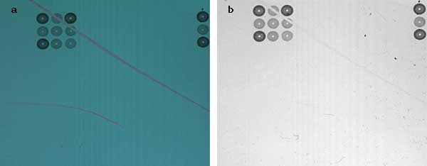
Figure 7. Polarization image (a) compared with a conventional, unfiltered image (b) of a printed circuitry. Contrast enhancement using polarization imaging reveals small scratches on the surface that cannot be detected with conventional imaging. Courtesy of Teledyne Dalsa.
Line scan polarization imaging combines the power of ellipsometry with truly lateral resolution. Developed in the 1970s, ellipsometry is a very sensitive optical technique with vertical resolution of a fraction of a nanometer. It has been widely used to determine physical properties of materials such as film thickness, material composition, surface morphology, optical constants, and even crystal disorder6,7. Imaging ellipsometry, developed later, adds a certain degree of lateral resolution. However, because of the point light source, it has a very small field of view (micron-millimeter) and is only suitable in microscopy. Line scan polarization imaging using a linear sensor and a linear light source overcomes this limitation.
Brewster’s angle imaging
The angle of incidence in ellipsometry is generally chosen to be close to the Brewster’s angle,
θB = arctan (n),
where n is the refractive index of the object and is wavelength dependent. For glass, n ≈ 1.52 and θB ≈ 56°, and for silicon, n ≈ 3.44 and θB ≈ 74° at 633 nm.
At the Brewster’s angle, reflection of p-polarized light is minimized and the difference between the reflectance of the s-polarized state and p-polarized state is maximized. This gives the highest sensitivity. When unpolarized light is incident under the Brewster’s angle and the camera is installed at the specular angle, the p-channel captures a dark signal while the s-channel still captures a normal signal from reflection. If completely p-polarized light is incident under the Brewster’s angle, the camera installed at the same angle captures a dark background. Any deviation on the surface due to defects or impurities, etc., will result in a bright region. High-contrast images can then be achieved. One challenge for line scan, though, is that the condition cannot be met when the field of view is much larger than the length of the sensor.
In summary, by combining high sensitivity of polarization phase detection and truly lateral resolution, line scan polarization imaging provides the detectability for next-generation vision systems in many demanding applications.
Meet the author
Xing-Fei He is senior product manager at Teledyne Dalsa Inc. in Waterloo, Ontario, Canada; email: [email protected].
References
1. X.-F. He and N. O (2012). Time delay integration speeds up imaging. Photonics Spectra, Vol. 46, Issue 5, pp. 50-54.
2. X.-F. He (2013). Trilinear cameras offer high-speed color imaging solutions. Photonics Spectra, Vol. 47, Issue 5, pp. 34-38.
3. X.-F. He (2015). Multispectral imaging extends vision technology capability. Photonics Spectra, Vol. 49, Issue 2, pp. 41-44.
4. V. Gruev et al. (2010). CCD polarization imaging sensor with aluminum nanowire optical filters. Opt Express, Vol. 18, pp. 19087-19094.
5. R.M.A. Azzam and N.M. Bashara (1987). Ellipsometry and Polarized Light. North-Holland Publishing Co.: Amsterdam.
6. X.-F. He et al. (1990). Optical analyses of radiation effects in ion-implanted Si: Fractional-derivative-spectrum methods. Phys Rev B, Vol. 41, pp. 5799-5805.
7. X.-F. He (1990). Fractional dimensionality and fractional derivative spectra of interband optical transitions. Phys Rev B, Vol. 42, pp. 11751-11756