Enhanced interface usability in modern design software enables even inexperienced lens designers to build well-performing optical systems.
Richard Pfisterer, Photon Engineering LLC
Optical design software allows the user to develop a configuration of optical elements that manipulate the trajectory of light for the purposes of creating an image, illuminating a target, coupling into a fiber, and so on. In many ways, it parallels the capabilities of popular CAD (computer-aided design) software for mechanical design but with a very significant difference: Optical design software can make changes to the optical elements to improve a performance metric. With enhanced usability possible in modern software interfaces, optical design software can make even an inexperienced lens designer capable of developing astonishingly well-performing optical systems.
Describing the optical system
Interestingly enough, for historical reasons, most optical design software systems do not define the optical system as a collection of optical elements but rather as a collection of optical surfaces positioned in space. There is an almost dizzying variety of surface types: spheres, conics, aspheres, cones, cylinders, toroids, zernikes, NURBs, various types of polynomials, and so on. Virtually any geometrical surface can be represented. Additionally, the user can select from fictitious or idealized optical elements such as thin lenses, lenses represented by ABCD matrices, or even simulated lenses based on eikonal theory that duplicate the aberration behavior of “real” lenses. However, even this expansive palette of surface types is insufficient for certain applications, and so in most cases the user can write customized code (usually in a higher-level language such as C or FORTRAN) to describe the surface and then link it to the optical design software as a DLL. The imagination of the user is really the only limit when it comes to describing geometry.
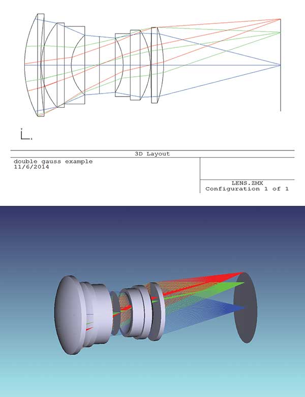
The user then assigns to each of these surfaces optical properties such as dispersive homogeneous, gradient or birefringent refractive indices, and diffraction grating lines, as well as transmissive and reflective coatings. Once these are assigned, these surfaces become representations of lenses, mirrors, prisms, and other recognizable optical components and affect the trajectory of light passing through them according to the assigned properties. Figure 1 shows the optical configurations of a centered double Gauss lens composed of two singlets and two doublets arranged around a central stop, and a folded, all-reflective system.

Figure 1. 3D solid models of two systems: a centered double Gauss lens and a folded, unobstructed all-reflective system, both showing the trajectories of rays originating from different field locations.
Although most optical systems have only a single detector and one path from the object to that detector, some systems employ beamsplitters and filters to create multiple optical paths addressing multiple detectors. Other systems such as classical zoom lenses have elements that move in space relative to each other to accomplish different optical tasks. These systems are called “multiconfiguration” or “zoom” systems, and users toggle between each of the configurations for both analysis and optimization as required.
Since custom optical elements can be expensive as well as not immediately available, most optical design software programs offer the user access to databases of commercial off-the-shelf (COTS) components available from numerous commercial vendors. Many successful prototype systems are developed by first designing with custom optical elements and then iteratively replacing the custom elements with readily available off-the-shelf parts, thereby taking advantage of the significant cost savings afforded by COTS.
Ray tracing
The fundamental calculation for all optical design software is ray tracing: the calculation of the exact trajectory of a light ray through the optical system. Because the image-forming properties of an optical system can depend upon very small differences (fractions of a wavelength of light, in most cases) in the trajectories of rays, ray tracing is generally performed to the highest level of accuracy possible on the computer.
Rays are traced from the object to the image through all optical surfaces. Very often, the object emits light according to a spectrum, and so rays are traced at different wavelengths to characterize the chromatic properties of the system. Less commonly, the polarization of the ray is important to a given calculation; ray-trace algorithms have been extended to include the trajectory of polarized light through both homogenous and birefringent materials, as well as polarizing elements such as linear polarizers, quarter-wave and halfwave plates, and so on. In very specialized applications such as photolithography and stellar interferometry, distributions of rays representing partially spatially coherent light can also be traced through an optical system.
In classical optical design, light originates at a point located either at infinity or proximate to the optical system and therefore describes a plane or diverging wavefront entering the optical system. However, with the advent of optical design for illumination systems, this concept had to be extended; modern optical design software can now represent light emitted by an LED, arc source, thermal source or another incoherent source. Depending upon their angular and spectral emission characteristics, these types of sources can require upwards of hundreds to thousands — even millions — of rays. Surprisingly, even this number of rays can be traced in seconds or minutes on modern computers (most vendors supply data files containing ray information to facilitate the integration of their sources into software for modeling.)
In traditional optical design, rays propagate from surface to surface in a sequential fashion, following the order in which the surfaces are defined. Again, to support optical design for illumination systems, it has been necessary to generalize the ray-trace algorithm to include “nonsequential” ray tracing, where the ray determines its trajectory not based upon the ordering of the surfaces in the software database, but instead from the dimensions and locations of the surfaces themselves. Since the rays do not know which surfaces will be intersected in which order, nonsequential ray tracing can be significantly slower than conventional ray tracing but represents the physical propagation of light through a generalized optical geometry.
Finally, there are applications where the use of geometrical rays fails to accurately describe the nature of the propagation of light through an optical system. In these cases, optical design software gives the user an alternative: a Fourier transform or beamlet-based propagation algorithm capable of modeling diffraction from apertures, interference, spatial filters, and other classical physical optics effects.
Optimization
Probably one of the most valuable features in modern optical design software is the ability to alter the prescription of the optical configuration to improve its performance for a given application. Broadly defined, this is the process of “optimization.”
Optimization algorithms have been in development for over 50 years, and today’s optical design software offers the user several powerful options. Most software offers a damped least-squares optimization algorithm that iteratively makes changes in the system to reduce the magnitude of a specified set of metrics; these metrics are collectively called the “error function,” “defect function,” “merit function” or similar nomenclature. However, the user may want to consider a larger parameter space (i.e., very dramatic departures from the starting point), so “global” optimization algorithms have been developed. These powerful tools can completely alter the initial optical system configuration; in some cases, they can add and remove elements in their search for a more optimum configuration. In most implementations, the algorithm searches for different solution spaces and then provides the user with a list of candidate designs from which the user can select and continue to refine.
As with optical surfaces, the variety of performance metrics that can be optimized is staggering: rms (root mean square) spot size, wavefront error, MTF (modulation transfer function), encircled energy, CIE color, irradiance uniformity, packaging, sensitivity to misalignment, beam clearance, ghost image suppression, tolerance to defocus, single-mode fiber coupling efficiency, local holographic grating frequency, cost, sensitivity to temperature changes, and so on. In those cases where the software lacks a specific metric to be optimized, the user can define one using construction and ray-trace database items.
Within the broad scope of optimization, most optical design software offers tools for specific applications. For example, most novice designers appreciate the ability of glass substitution/optimization tools to refine their glass selection; the refinement may be based upon image criteria but may also be related to cost, thermal expansion issues and availability, among others. Designers working with complex systems generally use software tools that interrogate the system looking for the optimum location(s) at which to place aspheric surface(s). Cam optimization software tells the zoom-lens designer exactly how groups of lens elements need to move to preserve image quality.
Analysis
There are numerous ways in which an optical system may be expected to perform, so it should not be surprising that there are numerous analysis options.
The simplest analysis option consists of diagnostics, usually of interest only to the optical designer. These include a single ray trace through the system, with the coordinates and direction of propagation (among other data) of the ray on each surface displayed. Aberration plots computed at specific locations across the field of view are very common in analysis, as these indicate the nature of the residual aberrations (image errors) present in the system and their magnitudes. Distortion plots, astigmatic field curves, and spot diagrams often round out a typical analysis.
More specialized analysis options are also available. Polarization ray tracing can compute the orientation of the electric field vector as the light propagates through the optical system. Aberration coefficients frequently offer an insight into those surface(s) responsible for high levels of aberration. Gaussian beams can be traced through the optical system to identify the locations of beam waists and astigmatic behavior. Multilayer coating properties such as reflection, transmission and absorption, among other properties, may be computed to compare with experimental data. Parameters (radii, thicknesses, refractive indices, aspheric terms, etc.) may be computed at multiple temperatures and the system reanalyzed to understand the changes in performance in different environments.
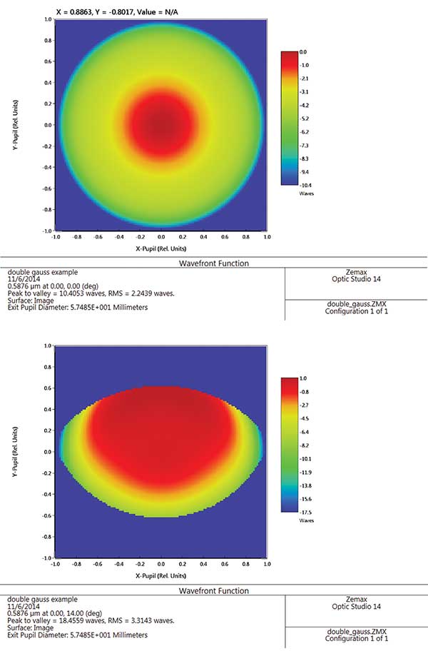
Next-level refinement of analysis options consists of calculations and data manipulations involving hundreds or thousands of traced rays. Examples include spot diagrams (plots of ray intersection coordinates on the image plane), point-spread functions, encircled-energy calculations, and ghost-image analyses. An illumination engineer simulating an LED or arc source propagating through a hybrid optic might trace several million rays to ascertain the level of irradiance uniformity at some observation plane. Modern multicore PCs are more than capable of tracing very large numbers of rays virtually instantaneously. Figure 2 shows the exit-pupil wavefront for a double Gauss lens on-axis and the edge of the field.

Figure 2. The wavefront at the exit pupil gives the lens designer a sense of the state of optical correction, as well as a visual clue of the amount of vignetting present as a function of field position.
Image analyses are probably the most sophisticated calculations commonly available in optical design software, and within this category are many different ways of evaluating imagery. For example, the designer may evaluate the MTF at several positions in the field across a spectral bandwidth. A designer working in the photolithographic industry might consider a partial spatial coherence resolution calculation to evaluate the resolution of a candidate system. In the photographic industry, a designer could perform an image simulation whereby an actual scene is imaged through an optical system to illustrate the resolution and residual distortion present in the final image.
Tolerancing and fabrication support
With the exception of theoretical design studies (such as the monochromatic quartet problem), the goal of most design efforts is to develop an optical prescription that can be fabricated at a reasonable cost. However, since fabrication is not an exact process, the resulting “as-built” radii, thicknesses, aspherics, refractive indices and so on are never exactly what the designer called for. Consequently, few fabricated systems deliver precisely the performance predicted by the optical design software. The challenge for the optical designer is to specify the degree to which each construction parameter must match its nominal value in the fabricated physical hardware while still delivering acceptable performance (keeping in mind that there may be hundreds of parameters in a modestly complex system).
Since the exact departure from the design radius of curvature, for example, can never be known, tolerancing algorithms depend upon statistics to bound the problem. There are two common approaches found in virtually all optical design software. The first is a “brute force” statistical analysis where random perturbations are applied to specific individual construction parameters (i.e., a lens thickness), to groups of construction parameters (i.e., to all of the radii, thicknesses, refractive indices, etc., in a group of lenses) or to the entire system geometry. Each construction parameter may have its own distribution of perturbations. For example, opticians tend to make lenses somewhat thicker than called for in case the lens must be reworked. Radii of curvature, on the other hand, have equal probability of being convex or concave to the test plate. The optical design software may generate and apply hundreds to thousands of realizations of perturbations to the system, acquire the statistics and present to the designer a summary of the probability of meeting a given level of performance.
The second common approach to tolerancing is to follow this same process but, instead of generating actual perturbations, applying perturbations algebraically. These algorithms, usually built around rms wavefront and MTF metrics, are much faster and allow the designer to conduct tolerance studies in minutes, whereas a brute-force approach might take hours or days. Of course, all algorithms have limitations, so many designers employ the algebraic approach early in the tolerance process and then subsequently verify all tolerance assignments with a brute-force analysis.
The exact metric to be toleranced depends upon the application. A tolerance photographic objective may have to meet an MTF requirement. An astronomical telescope camera system working with a CCD detector may have an encircled-energy requirement relative to the pixel dimensions. A reconnaissance camera could very well have a distortion tolerance. In an illumination system employing an LED and hybrid optic, the divergence and total power contained within the emitted beam may be the tolerance metric.
Ultimately, tolerancing is a trade-off between optical system performance and cost of fabrication. There is rarely a unique set of tolerances for a given application, and frequently a designer has no hard evidence that his/her tolerances are optimal. In many cases, the selection of tolerances is determined by experience, as well as by outputs from optical design software.

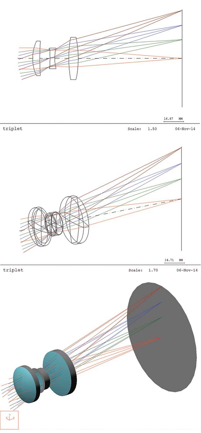
Figure 3. Example of increasing graphic sophistication, from a simple cross-sectional line plot to a 3-D wireframe to a 3-D solid model in modern lens design software.
User interface
Since traditional optical design involves the propagation of light sequentially through a collection of surfaces, most optical design software arranges the construction data in a spreadsheet fashion, where each row of data corresponds to a particular surface.
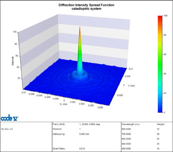
Optical design software can provide the user with a seemingly endless number of graphics: two- and three-dimensional views of the optical system (including the ray traces, as shown in Figure 3), transverse ray-aberration plots, wavefront plots, spot diagrams, point-spread function plots, MTF curves, encircled-energy plots, lateral chromatic-focus plots, Gaussian beam profile plots and so on. The optical designer likely must convey information to a broad audience (i.e., investor, client, fabricator, supplier, advertising agent, peer group, etc.), so software developers have made virtually all common analyses literally a push-button away. Figure 4 shows the axial point-spread function for a catadioptric system; a systems engineer may convolve this data with a detector pixel in order to compute energy on detector (EOD).

Figure 4. The axial polychromatic point-spread function for a catadioptric system that may be further processed by a systems engineer in order to compute energy on detector (EOD).
However, there are instances where what the optical designer does is simply a piece of a larger design/analysis effort. Accordingly, most optical design software has the ability to interface directly via .COM or .NET to other, nonoptical applications such as MatLab, LabView, Mathematica, etc. In these cases, the optical design software frequently is queried for a specific calculation in response to an action taken by another piece of software involved in the analysis (e.g., a surface perturbation resulting from a thermal shock to the system). Simulations of this type can quickly become extraordinarily complex, but they provide the analyst with valuable information on how the system will perform in the real world.
Becoming an optical designer
Modern optical design software is immensely capable and flexible, giving the experienced lens designer a tool for virtually limitless creativity. However, it will not make an unskilled user a lens designer any more than a hammer makes an unskilled user a carpenter. Unfortunately, developments in graphic software interfaces over the past 30 years have, in many cases, given the impression that lens design is simply a matter of “pushing a few buttons,” but nothing could be further from the truth.
Optical design has variously been called art, science, or a creative process. However, the software simply takes its direction from the user. Ultimately, the skills, experience, and insights of the optical designer are what allow the design to evolve from concept to reality.