Full company details
MKS Ophir
Unit of MKS Instruments Inc.
Light & Measurement
 3050 North 300 West
North Logan, UT 84341
United States
Phone: +1 435-753-3729
Fax: +1 435-753-5231
Toll-free: +1 866-755-5499
Antireflection Coatings for High-Power Fiber Laser Optics
Photonics Spectra
Sep 2020Low-absorption antireflection coatings are critical to the performance, reliability, and lifetime of optics used in high-power fiber lasers.GHEORGHE HONCIUC, EMILIANO IOFFE, AND JURGEN KOLBE, OPHIR OPTICS GROUP, MKS INSTRUMENTS INC.
High-power kilowatt-level fiber lasers operating between 1.0 and 1.1 µm find frequent use in macro-materials processing applications, such as cutting and welding metal sheets. The nature of these applications requires laser optics to perform properly at correspondingly high laser powers and power density levels. Minimizing losses due to absorption is therefore of crucial importance to laser reliability and performance.
Achieving this requires a clearer understanding of the materials, coating
technologies, and measurement techniques used for the manufacturer of high-performance, low-absorption fiber laser optics.
Absorption and reflectance
Absorption of laser radiation leads to increased temperature and a correspondingly higher refractive index of the optics. This, in turn, can change the properties of the transmitted laser beam and impair the performance of the manufacturing process. In addition, heat can cause internal mechanical stress and eventually damage the optics.
The most common raw material used for high-power laser optics is fused silica, which offers sufficiently low absorption. The quality of the finished optics is more dependent on the quality of the surface-polishing treatment and especially on the absorption of the antireflection (AR) coatings applied.
AR coatings must offer minimal residual reflectance. Otherwise, reflected radiation can heat up the processing head and further impair the performance of the manufacturing process. AR coatings offering lower absorption can also contribute to a longer service life and reduced downtime of the laser machine.
A look at raw materials
Fused silica materials can be divided into two categories defined by absorption
levels: above and below 1 ppm/cm
1. Higher-performing materials that offer absorption below 1 ppm/cm can come at a greater cost. When possible, it is prudent to use materials that deliver sufficiently good results.
Since the absorption of high-quality AR coatings can be <10 ppm, it should be noted that fused silica >1 ppm/cm can contribute significantly to the overall absorption of the coated optics. Bear in mind that the polishing process can also affect absorption. To assess the quality of a coating, it is therefore necessary to measure the absorption of the optics before and after coating.
In addition to absorption, scattering caused by surface imperfections can also affect the function of high-power laser optics. Therefore, optical surfaces need to have low roughness and minimal defects. A suitable standard for surface roughness would require <1 nm for planar and spherical surfaces, and less than 5 nm for aspherical surfaces. Figure 1 represents the measurement of a plane-polished surface.
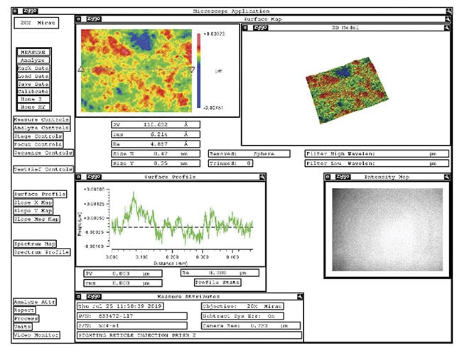
Figure 1. A roughness measurement of a plane-polished surface taken with a Zygo NewView interferometer. Courtesy of MKS Instruments.
Coating technologies
The numerous methodologies for producing coatings with very low absorption losses include standard electron-beam (e-beam) gun evaporation, ion beam-assisted deposition (IAD) using e-beam gun evaporation, ion-beam sputtering (IBS), plasma-assisted reactive magnetron sputtering (PARMS), sol-gel techniques, atomic layer deposition, molecular beam epitaxy (MBE), and application of AR nanotextures.
Technical Data for AR Coatings for 1-μm High-Power Fiber Lasers

*Upper tolerance level for production; real values can be significantly lower.
**17 kW is valid only for protection windows. Upper level strongly depends on environmental working conditions.
Among these methods, coatings produced with standard e-beam gun evaporation or IAD provide excellent results at moderate costs. Common coating materials include hafnium(IV) oxide (HfO
2), tantalum pentoxide (Ta
2O
5), and silicon dioxide (SiO
2).
One major challenge in the production of low-absorption coatings is ensuring good uniformity of properties, such as thickness, refractive index, and absorption on all optics batched in a calotte, which typically measures 760 mm in diameter. This requires careful control and optimization of all parameters of the evaporation process, as well as testing of optics from various locations in the calotte.
The simplest AR coating — which, in theory, enables zero residual reflectance — is the v-coating, named after the V shape of the reflectance curve (red curve in Figure 2). It consists of one layer with a high refractive index (HfO
2, blue curve) and one layer with a low refractive index (SiO
2, green curve). Because the layer made of the relatively strongly absorbing high-index material is quite thin, total absorption of the coating is very low (see the table above called Technical Data for AR Coatings).
High transmittance for both 1 µm and for a laser pointer (typical wavelength: 650 nm) can also be achieved with a coating consisting of two layers, but only with increased thickness of the high-index layer and therefore higher absorption (blue curve in Figure 2). With such coatings, it is possible to achieve a residual reflectance below 0.1% for a single wavelength in the range between 1030 and 1070 nm, and below 0.2% for the entire range between 1030 and 1070 nm.
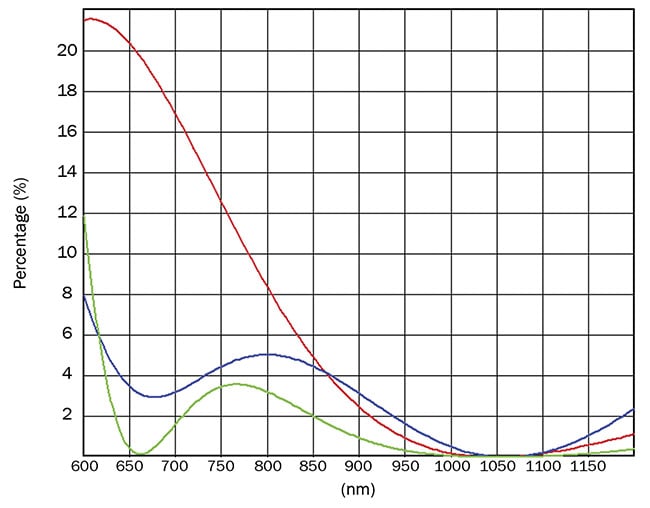
Figure 2. The simplest AR coating, which theoretically enables zero residual reflectance, is the v-coating (red curve). It consists of one layer of a high-refractive-index material, such as HfO2 (blue curve), and another layer of a low-refractive-index material, such as SiO2 (green curve). Because the layer made of the relatively strongly absorbing high-index material is quite thin, total absorption of the coating is very low. Courtesy of MKS Instruments.
Maximum laser power for lenses depends on surface curvature. When coating curved lens surfaces, it is not sufficient for the residual reflection to be minimized only for the laser wavelength because thickness of the coating is greatest in the center of the lens surface and diminishes with increasing distance from center. The angle of incidence of the laser beam follows a similar rule: It is normal in the center of the lens and increases with distance.
Both effects cause the reflectance curve to shift to shorter wavelengths. To compensate for this, reflectance must be as low as possible, even in a suitable range above the laser wavelength. It is also important to remember that coating thicknesses can differ slightly from one position to another in the calotte.
Since this requirement cannot be met with a two-layer coating, some suppliers have developed four-layer coatings with reflectance lower than 0.1%, between 1020 and 1090 nm (green curve in Figure 2). Figure 3 (red curve) illustrates one such multilayer coating that was developed for lasers that operate at extremely high laser powers above 12 kW. The coating delivers residual reflectance of less than 0.05%, from 1030 to 1120 nm. Figure 3 also shows the reflectance curves of another v-coating and another two-layer system, with increased thickness of the high-index layer.
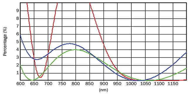
Figure 3. Data showing a multilayer AR coating (red curve) with reflectance of less than 0.05% at 1030 to 1120 nm. It comprises an AR v-type coating of Ta2O5 material (blue curve) and an AR coating consisting of thick high-index HfO2 material (green curve). Courtesy of MKS Instruments.
AR coatings offering lower absorption can contribute to a longer service life and reduced downtime of the laser machine.
The most important technical data regarding the coatings is summarized in the table. The absorption values listed are among the lowest that can be achieved reliably with IAD. Lower values can be achieved with IBS, but because of this method’s high cost, it makes sense for only a few special applications.
Measuring absorption
Absorption measurements often rely on a calorimetric system, as illustrated in Figure 4. The system irradiates the sample (window or lens) for 3 min with a 500-W continuous-wave fiber laser operating at 1030 nm and monitors the temperature increase of the upper surface of the sample using a pyro sensor working at 8 to 12 µm.
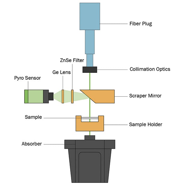
Figure 4. A schematic showing a calorimetric system for absorption measurements. Courtesy of MKS Instruments.
An advantage of this method is that it provides direct information about the temperature increase of the sample when irradiated with a high-power laser. However, measurement data for samples of various sizes cannot be compared directly. This means that an individual tolerance level must be defined for each product. Also, it is extremely difficult to determine the absolute absorption of the sample from the measurement data.
For these reasons, photothermal
common-path interferometry (PCI)
2 is also used to measure absorption. This method can measure absorption at any location within the sample by focusing a pump laser (wavelength 1 µm) on the position to be measured. It causes local heating with a corresponding local increase of refractive index. This creates interference effects on a test laser beam operating at 633 nm. Measuring and evaluating these effects determines the local increase of refractive index and temperature increase.
Figures 5 to 8 show typical measurement curves that these two methods obtained on a window made of Corning 7980 fused silica (50-mm diameter and 5-mm thickness). All measurements were made on the same optics before and after coating. The PCI scans shown in both figures illustrate the spatial dependence of absorption for a scan from one surface, through the optics, to the second surface. The absorption maxima in the area of the coatings are clearly visible in Figure 6; the absolute absorption is approximately
4 ppm at each surface. Figures 7 and 8 show the results for the corresponding calorimetric absorption measurements.
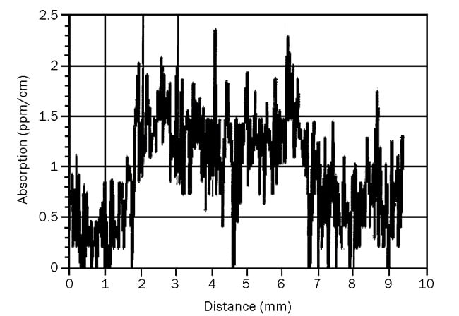
Figure 5. Data illustrating a PCI absorption measurement for a window fabricated from uncoated Corning 7980 material. Courtesy of MKS Instruments.
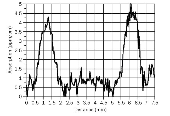
Figure 6. Data showing a PCI absorption measurement for a window fabricated from Corning 7980 that had AR coating applied to both surfaces. Courtesy of MKS Instruments.
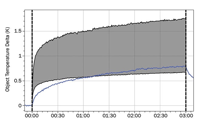
Figure 7. Data showing calorimetric measurement of the temperature increase for an uncoated window fabricated from Corning 7980 fused silica. Courtesy of MKS Instruments.
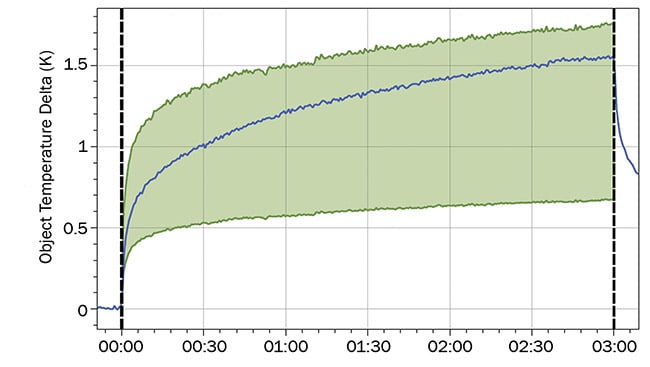
Figure 8. Data showing calorimetric measurement of the temperature increase when testing a window fabricated from Corning 7980 that had AR coating applied to both surfaces. Courtesy of MKS Instruments.
The calorimetric system offers an easier solution for gathering absorption measurements for quality assurance. The PCI method is suitable for special purposes, such as calibrating calorimetric measurement data.
AR coatings evolve
Low-absorption AR coatings for optics are beneficial for many applications with high-power fiber lasers. Absorption measurements made with high-resolution methods, such as those described above, allow for precise measurement results down to the parts per million range.
Coatings can be further optimized to meet market requirements, including for:
• Absorption.
• Residual reflectance.
• Suitability for optics with curved surfaces.
• Transmittance in the visible for laser pointer.
• Suitability for high continuous-wave laser powers.
• Production cost.
Low-absorption coatings have demonstrated proven performance at laser powers up to 17 kW in applications such as macro-materials processing. To keep up with the challenges surrounding higher laser powers, further improvements and developments are required.
Meet the authors
Gheorghe Honciuc, Coatings Engineering Group manager, Ophir Optics Group at MKS Instruments Inc., has a Master of Physics from Alexandru Ioan Cuza University. For the last four decades, he has specialized in optical coatings.
Emiliano Ioffe, process development and engineering manager, Ophir Optics Group at MKS Instruments Inc., started on the manufacturing floor, specializing in optical component fabrication technologies. He has also managed the IR components engineering department and is now responsible for process development.
Jurgen Kolbe, Ph.D., sales laser optics Europe, Ophir Optics Group at MKS Instruments Inc., has over 20 years of experience in electro-optics, specializing in optical coating process and laser optics products. He holds a doctorate in physics from the Leibniz University of Hanover.
References
1. F. Nürnberg et al. (Nov. 23, 2015). Bulk damage and absorption in fused silica due to high-power laser applications. Proc SPIE, Vol. 9632, Laser-Induced Damage in
Optical Materials, Boulder, Colo.,
https://www.doi.org/10.1117/12.2194289.
2. A. Markosyan et al. PCI technique for thermal absorption measurements,
https://dcc.ligo.org/public/0037/G080315/000/G080315-00.pdf.