Full company details
MKS Ophir
Unit of MKS Instruments Inc.
Light & Measurement
 3050 North 300 West
North Logan, UT 84341
United States
Phone: +1 435-753-3729
Fax: +1 435-753-5231
Toll-free: +1 866-755-5499
Measuring High-Power Materials Processing Lasers with Camera-Based Beam Profilers
Photonics Spectra
Jul 2020New methods of real-time flaw detection offer end users improved materials processing, increased efficiency, reduced waste, and a better overall lean manufacturing experience.CHRISTIAN DINI AND JOHN MCCAULEY, OPHIR

From cutting steel to drilling via holes in silicon to marking plastic, a wide range of materials processes now use high-power lasers. Ever-growing demands for increased productivity and reduced waste require that the laser process be stable and predictable. Therefore, the industrial laser — like any tool used in precision manufacturing — must be tightly monitored to maintain peak performance.

Historically, a beam profiler that measures and analyzes high-power lasers has cost several tens of thousands of dollars to purchase. A recent alternative to these legacy beam profiling systems is the high-resolution CCD camera, which is relatively inexpensive and fast. CCD cameras capture detailed beam information such as spot size, beam quality, and stability — at video rates — and they also monitor performance across the work field. Additionally, the cameras reduce costs and open the door to new quality and maintenance strategies that protect laser systems investments (Figure 1).

Figure 1. Software captures four characteristics of a 6-KW fiber laser in a 4-s pulse (a) and the beam’s waist, including the static (blue) and dynamic (green) indicators of focused spot location (b). The four graphs show: absolute measurements of several laser characteristics (1); 1D profiles of the laser, illustrating energy distribution across the beam at the working plane (2); the relationship between the time-based measurement of focus shift (~8.4 mm upward in 4 s) (3); and the increase in the beam size at the work plane (4). The increase in beam size translates to a 41% decrease in power density over the 4-s beam-on duration. Courtesy of Ophir.
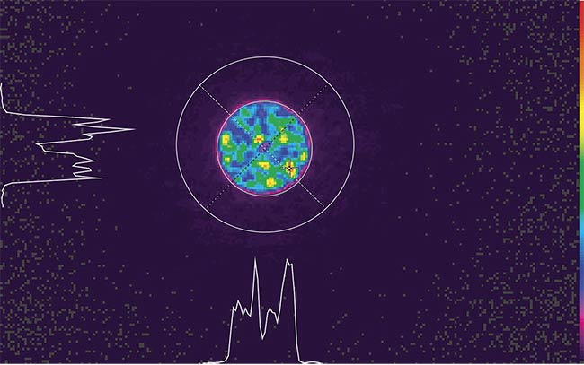
Because high-power lasers in materials processing can be challenging to use, it’s important for both OEMs and end users to be proactive, to check/improve beam quality regularly, and to understand the many advantages camera-based beam profilers can offer (Figure 2).

Figure 2. Measurements made with a CCD camera reveal a focus spot beam profile with no quality problems (opening image), and a focus spot beam profile with quality problems (above). Courtesy of Ophir.
Beam parameters of concern
Many laser parameters are taken during the laser’s life cycle and different measurements mean different things along the way. For instance, laser quality measurements such as M
2, BPP (beam parameter
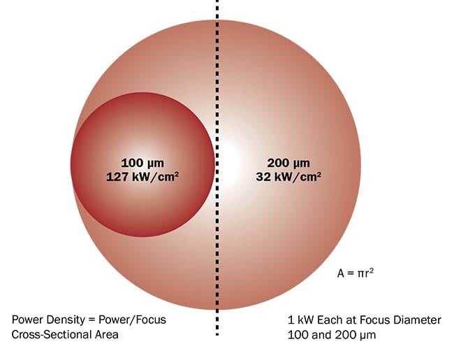
product), and Rayleigh length are extremely important to take during the development of the laser source. However, these measurements usually don’t mean much once the laser is put into production. At the same time, measurements such as laser power and focused spot size are important to understand at all stages of the laser’s life because these two measurements define the laser’s power density (Figure 3).

Figure 3. The relationship between focus size and power density. When the focus diameter is half as large, it results in an intensity that is 4× higher. Courtesy of Ophir.
Power density can be defined as the amount of laser light applied with respect to the size of the beam at the point of material processing. It is a laser characteristic expressed in watts (or variations of watts) per centimeter squared (W/cm
2) and it measures how the laser is interacting with the material being processed. Understanding this characteristic is vital to the success of the laser’s application.
Protecting laser investments
In traditional manufacturing processes, ready-made parts are qualified and bad parts are rejected. Because of digitalization and today’s trend toward green manufacturing, it is more important than ever to understand how a laser system works and to take frequent measurements of
the laser’s characteristics, such as beam parameter and power density. CCD cameras capture these characteristics during parts processing and enable manufacturers to discover errors sooner, thus preventing or greatly reducing poor laser performance during processing. Tracking
laser performance with CCD cameras also enables measurements to be taken between the processing of parts, such as during loading and unloading, which helps keep the total processing time consistent while increasing yield.
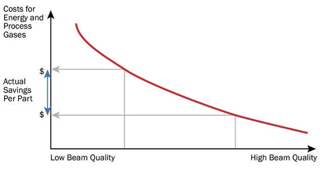
Even with the availability of affordable measurement solutions, laser manufacturing faces a paradox: Investments worth hundreds of thousands of dollars are made in laser systems, yet these investments are left unprotected because the measurement technology to support optimal operation is perceived as either too complicated or too expensive. The reality, however, is that a relatively small investment in laser measurement technology is extremely valuable. When viewed as protection of the end user’s large investment in the system, measurement technology actually supports cost reductions in ownership and operation (Figure 4).

Figure 4. The relationship between focus quality and cost per part in industrial laser processes. Courtesy of Ophir.
Most companies are seeking ways to more responsibly consume energy. They analyze and streamline their processes to reduce production times and materials. Still, there is some resistance to measuring laser systems, which may be a reaction to: 1) the investment needed for the measurement equipment, 2) the difficult operation of the measurement device and the possibility of damaging it, and/or 3) the time required to make the measurement, particularly if it’s done at the expense of production time. However, understanding laser systems with these efficiency factors in mind increases knowledge and makes analysis of the system’s performance easy and natural.
Measuring high-power lasers
In general, three methods are employed to measure high-power laser performance. The first involves beam profiling and includes two of the most common approaches over the past 20 years: the scanning slit beam profiler for low and medium powers, and the scanning tip with a pinhole for higher powers, which samples a small portion of the beam and presents it to a single-element detector. For both, the rotational and translational scanning of the pinhole through the beam creates a 2D image of the beam profile. This method requires large-scale equipment with moving mechanical parts, a water chiller, expert knowledge on the part of the operator, as well as sufficient time to complete the measurement. Since this equipment is relatively expensive to purchase and maintain, and slow to take measurements, it is not very practical in production environments.
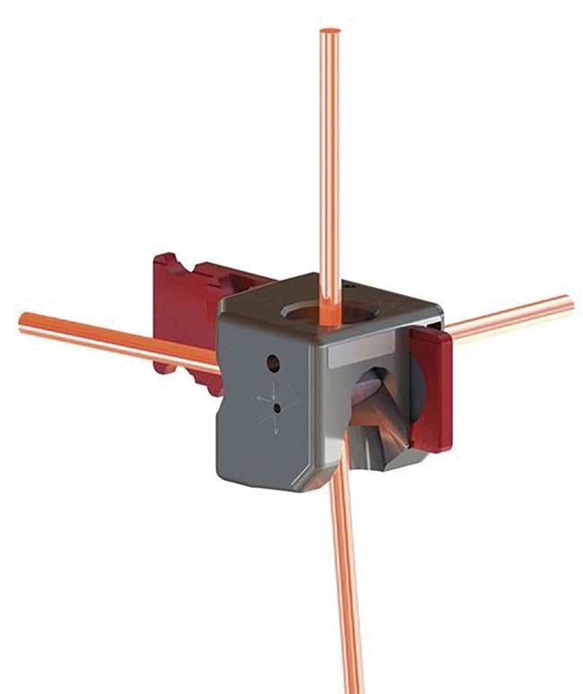
The second method is newly available and involves an indirect or noncontact measurement system that does not interact with the beam. This technique is based on imaging the beam’s Rayleigh scattered light from the side, and then measuring the entire beam caustic around the focal spot in real time. This technology is an industry first and shows the whole beam caustic at once with a time resolution, at video rates (Figure 5).

Figure 5. New noncontact beam measurement options are based on imaging Rayleigh scatter. Courtesy of Ophir.
The third method moves high-power beam measurement one step further, increasing speed and reducing cost. This latest advancement takes direct beam measurements with a fast, one-shot, low-cost, low-power, and familiar CCD beam profiler, and combines it with many orders of magnitude of optical attenuation. This approach includes a beam attenuation system designed for focused spot beam analyzers and combines dual sampling optics and neutral density filters for beam attenuation before the focused spot reaches the camera. The measurement system’s beamsplitter is designed for high-power lasers and employs newly engineered sampling optics that allow measurement of NIR (1000 to 1100 nm) focused or collimated laser beam profiles up to 5 kW or 15 MW/cm
2.
With this technology, a low-cost system can provide the usual 2D and 3D beam profiles, as well as the capability for fast measurements of both an image integrated over a certain period of time and the full beam profile with dynamic changes, at video rates (Figure 6).

Figure 6. A compact, camera-based focus spot beam analyzer. Courtesy of Ophir.
Industry 4.0 requires production to move away from two-or-more-step processes that include locating and then separating low-quality parts at the end stage. A bad weld, for example, can be hard to find. And, if a weld seam is bad, it may jeopardize expensive components. What’s more, the cost of part rejection is high, as is the quality inspection. With recent advancements in digitalization, however, new processes will simply eliminate the
production of bad parts altogether. Therefore, operating a laser system at near optimum performance is key to all-around improvements — in parts quality, in general production capabilities, in reject reduction, and in cost savings on running machinery.
Tighter process control requires more process data that is more frequently captured. Measuring power density is the key to understanding the optical performance of any laser materials processing system. Focal shift can have a massive impact on delivered power density; therefore, a fast measurement system that captures data over time is required. Such real-time
measurement and short times to capture data will keep production cycle time the same or improve it.
CCD cameras are a fairly inexpensive
yet fast beam profiling solution that can
provide UV to NIR measurements in low-power applications. Combining this imaging technology with the latest developments in beam attenuation has produced a quick and easy beam profiler that can overcome the major barriers for laser beam monitoring, including time to set up and time for measurement. It supports performance monitoring where it is needed most, at the end user facility. Monitoring trend lines of power density enables narrower process windows and operation of the laser system closer to its optimum specifications. This saves energy and provides better results. Camera-based beam profiling technology has created a new path to automated measurements at an improved level of granularity for every part in the production process, even at rates of thousands of parts per day, from job shops to production, and from operators to field service.
Meet the authors
Christian Dini is director of global business development at Ophir. He has an engineering degree from Technische Fachhochschule München; email:
[email protected].
John McCauley is key automotive accounts manager at Ophir. He has a BSBA from
Indiana Institute of Technology; email:
[email protected].