Silicon photomultipliers and photomultiplier tubes each boast unmatched sensitivity, yet their distinct characteristics make them suited for different uses.
SLAWOMIR PIATEK AND EARL HERGERT, HAMAMATSU CORPORATION
Developed in the early 1990s, the silicon photomultiplier (SiPM) is a solid-state photodetector whose sensitivity to light rivals that of a photomultiplier tube (PMT) in a regime where a few hundred photons per second illuminate the detector. A very high (~106) internal gain gives SiPMs and PMTs extraordinary photosensitivity unmatched by any other photodetector. Although they have similar gains, SiPMs have several other attributes making them attractive as a detector choice vis-à-vis PMTs, including a low operating voltage (20 to 60 V) and immunity to magnetic fields. SiPMs are also small, rugged, low cost, and do not require warm-up time or exhibit hysteresis.
Even with these potential advantages, SiPMs aren’t likely to relegate PMTs as obsolete in the future; rather, they’ll remain complementary to one another. Comparing the detectors shows each of their unique and distinct characteristics that determine which technology is a better choice for a particular application.
Detector components
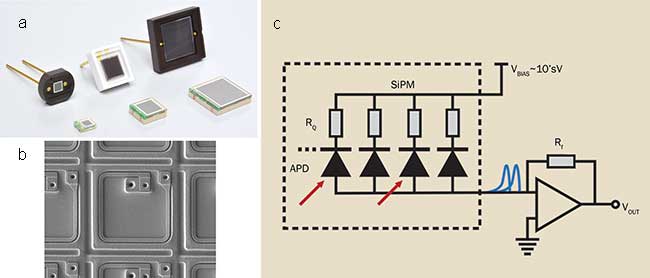
An SiPM is an array of microcells. Each microcell is a series combination of a silicon avalanche photodiode (APD) and a “quenching” resistor. Because all the microcells are connected in parallel, an SiPM has two contacts: a cathode and an anode. Depending on the design, the size of a microcell ranges from 10 × 10 μm2 to 100 × 100 μm2, their numbers ranging from a few hundred to a few tens of thousands. The total active area ranges from 1 × 1 mm2 to 6 × 6 mm2 (Figure 1).

Figure 1. Various SiPMs (a); a single microcell (b). The loop-like structure on the surface is the quenching resistor; SiPM (represented by its equivalent electrical circuit) biased by an external voltage source and connected to a transimpedance amplifier (c).
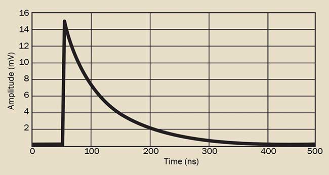
Under typical operating conditions, the applied reverse-biased voltage (VBIAS) is a few volts above the breakdown voltage (VBD) of the APDs. This makes the APDs operate in Geiger mode. Typical values of VBIAS are on the order of a few tens of volts. Overvoltage, the key parameter controlling the operation of an SiPM, is the difference between VBIAS and VBD. Its typical value, optimized for the best performance, is 2 to 6 V. A photon incident on the active area is absorbed within the semiconductor layers of the APD, resulting in formation of an electron-hole pair. One of the two charge carriers drifts into the microcell’s high-field region where it triggers an avalanche, subsequently quenched by the resistor. The result is a current pulse from the anode as illustrated by blue waveforms (Figure 1c) and by the actual waveform — average of 1000 and converted to a voltage waveform (Figure 2). An SiPM is effectively a light-driven current source.

Figure 2. Average of 1000 single-photon waveforms from a Hamamatsu S13360-6050CS SiPM. The data is taken with a 1-GHz oscilloscope (50-Ω input impedance). The SiPM has 14,400 50 × 50 μm2 microcells giving 6 × 6 mm2 of total active area.
The exact shape of the waveform depends on the electrical properties of the microcell, overvoltage, and detection circuit. The rise and fall times typically are a few ns and ~100 ns, respectively. They are both independent of overvoltage, but increase with the cross section of a microcell. Amplitude of the current pulse is proportional to the ratio of the over-voltage and quenching resistance. The area under the pulse, expressed in number of electrons, equals the gain. With a typical value of 105 to 106, gain is linearly proportional to the product of the overvoltage and the cross section of a microcell.
A PMT is a vacuum tube with three essential components: a photocathode, a system of dynodes, and an anode. PMTs come in a wide variety of designs and sizes: the diameter of the active area ranges from a few mm to tens of cm (Figure 3).

Figure 3. Family portrait of PMTs (a); schematic of a hypothetical six-dynode PMT biased with a resistive voltage divider and connected to a transimpedance amplifier (b).
A schematic shows a hypothetical six-dynode PMT biased with a resistive voltage divider (Figure 3b). Its output is fed into a transimpedance amplifier. In this anode (P) grounded scheme, the lowest potential (most negative) is at photocathode (K). Potential increases (becomes less negative) as one moves from the photocathode through the dynodes (Ds) toward the anode.
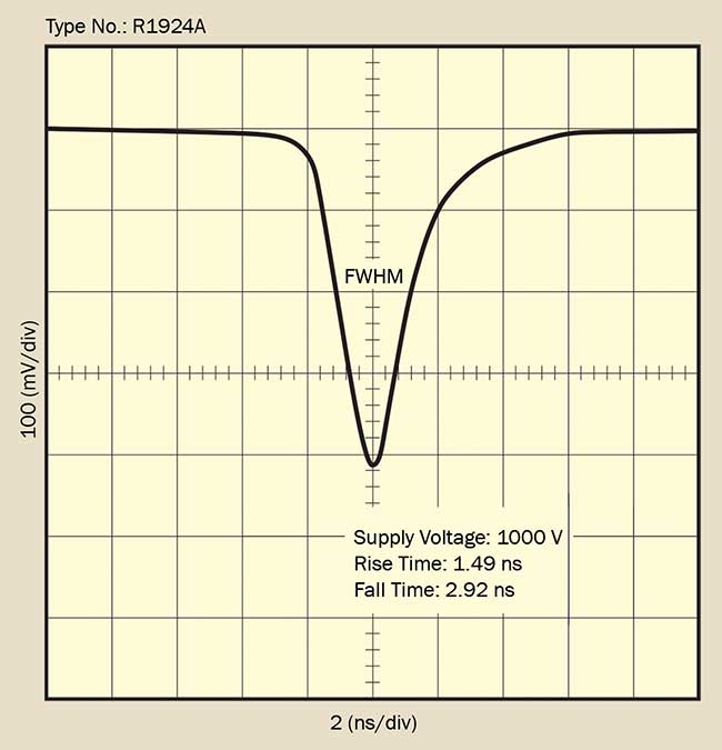
The operation of a PMT relies on two phenomena: extrinsic photoelectric effect in the photocathode and secondary electron emission in the dynodes. The first is responsible for the emission of a photoelectron in response to incident photon, while the second is responsible for the chain-multiplication of electrons, triggered by the photoelectron. The output is also a current pulse (Figure 4) whose shape depends on the PMT’s overall size, geometrical configuration of the dynodes, type of voltage divider, and value of the bias voltage.

Figure 4. Example of single-photon waveform from a PMT (Hamamatsu R1924A). Taken with a 1-GHz oscilloscope (50-Ω input impedance). FWHM: full width half maximum.
The gain of a PMT follows a power-law dependence on the supply voltage; the exponent equals approximately the number of dynodes. When compared with single-photon waveforms from an SiPM (Figure 2), those from a PMT (Figure 4) are narrower, more symmetric, and of larger amplitude for the same gain. These characteristics give the PMT an advantage in detection systems employing digital photon counting.
Photon detection efficiency
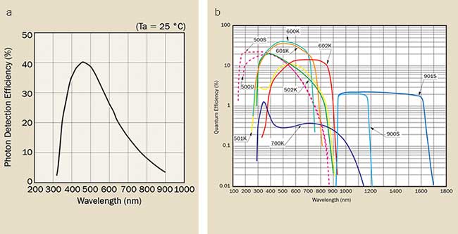
Spectral sensitivity, the measure of a photodetector’s ability to respond to light, is of primary importance when designing any detection system. If a photon of wavelength λ strikes the active area of an SiPM, the probability of ensuing output is given by photon detection efficiency (PDE). PDE is a function of wavelength (Figure 5a), and overvoltage. The figure shows that an SiPM has sensitivity in the 300- to 900-nm range, with peak PDE around 450 nm.
For a PMT, the quantum efficiency of the photocathode is the probability that electrons will be emitted into the vacuum in response to incident photons. This probability, for a given photocathode material, is a function of wavelength. Since there are a great variety of photocathode materials, the spectral coverage for the entire family of PMTs is in the range of 150 to 1700 nm (Figure 5b). Comparison of both panels shows that SiPMs are competitive with PMTs only in the 300-to 900-nm spectral range, where their sensitivities are similar.

Figure 5. Typical photon detection efficiency versus wavelength for an SiPM operating at the recommended overvoltage (a). Reducing overvoltage lowers the PDE. Quantum efficiency versus wavelength for several types of photocathodes (b).
The competitiveness may widen in the future if other semiconductors, not just silicon, will be used in constructing solid-state photomultipliers. Automotive distance lidar (light detection and ranging) is an application that would benefit from the development of SiPMs with higher sensitivity at 905 nm (currently 7%) and 1550 nm (currently no sensitivity).
Excess noise factor
Every photodetector contributes noise to the measurement. The two main sources of noise in SiPMs and PMTs are dark current shot noise and multiplication noise, commonly represented by multiplicative excess noise factor (F). In complete darkness, both detectors generate output current pulses, called dark counts. A dark count is indistinguishable from that due to absorption of a photon. The majority of dark counts in an SiPM are due to thermally generated charge carriers triggering avalanches, whereas in a PMT they are a result of thermionic emission of electrons from the photocathode.
Higher temperature leads to a larger dark count rate in both detectors. Raising the bias voltage while at constant temperature increases the dark count rate in an SiPM but not in a PMT. The dark count rate per unit active area is higher in an SiPM than in a PMT. As an example, the dark count for the Hamamatsu S13360-6050 SiPM (14,400 of 50 × 50 μm2 microcells, 6 × 6 mm2 active area) is about 56 × 103 counts per second per mm2, while the dark count for the Hamamatsu R928P PMT (8 × 24 mm2 active area) is 3 counts per second per mm2.
Within the overlapping spectral response range, an SiPM has substantially higher noise induced by dark counts than a PMT. The large active area and low dark count rate of a PMT makes it a better detector in a regime where only tens of photons per second illuminate the active area, such as analytical bio- and chemiluminescence, both of which often produce faint and diffuse light.
Gain variations give rise to multiplication noise and, thus, excess noise factor F > 1. Excess noise is the penalty for having intrinsic gain. Optical crosstalk accounts for the majority of excess noise in an SiPM. It occurs when an avalanche (primary) in a microcell triggers a nearly simultaneous avalanche (secondary) in one or more neighboring microcells. Consequently, the output current pulse is a chronological superposition of the primary and all secondary avalanches. The probability of crosstalk is about 2% or higher depending on overvoltage and microcell size. A typical value of F is about 1.3 or less.
In a PMT, the statistical nature of the secondary electron emission primarily gives rise to gain variations and therefore to excess noise comparable to that of an SiPM. Portable radiation detection and monitoring for homeland security, cargo inspection, or environmental control requires a photodetector that is small, rugged, easy to couple with a scintillator, and whose gain has minimal variation. An SiPM is an excellent choice here.
Dynamic range represents the scale of input light levels measurable by a detector. A detector’s internal noise floor imposes a limit on the lowest level, whereas saturation imposes a limit on the highest. Linearity is a related concept; if a detector’s output (in arbitrary units) is linearly proportional to the input light level, the detector is said to be linear. A perfect detector would have an infinite dynamic range and absolute linearity. Neither SiPM nor PMT exhibit such ideal characteristics.
The finite number of microcells in an SiPM has the greatest impact on its dynamic range and linearity. Suppose that δ-like light pulses uniformly illuminate the entire active area of an SiPM. Experiments have shown that if the product of the number of impinging photons and the PDE, or the number of photoelectrons, begins to exceed about 60% of the total number of microcells, the upper limit of the dynamic range and linearity is being reached. Using Hamamatsu S13360-6050 SiPM with 400 microcells per mm2 as an example, the upper limit of the dynamic range is 240 photoelectrons per mm2 or about 9 × 10³ photoelectrons per device. Optimizing dynamic range and linearity by selecting an SiPM with a higher density of microcells involves trade-offs for gain and PDE.
In a PMT, dynamic range and linearity depend on the type of the photocathode (semitransparent versus reflection), dynode structure, and the type of the voltage divider. For example, the maximum average current of Hamamatsu R928 PMT is 0.1 mA and a typical anode dark current is 3 nA, giving a dynamic range of about 3 × 10⁴. PMTs optimized for the highest dynamic range and linearity are available. In this comparison, the SiPM is at a disadvantage, which impedes its adoption in flow cytometry, a popular technique in medicine and biotechnology for analyzing microscopic cells and particles.
The photodetector’s response time, or transit time, is the time from the instant a photon arrives at the active area to the instant the resulting current pulse reaches its maximum value. The histogram of the measurements of a single-photon transit time has a Gaussian-like distribution; its width represents time jitter — the extent of transit time variation. The smallest possible jitter is a decisive characteristic in those applications that rely on techniques such as coincidence detection, direct time-of-flight of light, or light-triggered gated measurements. Jitter in both devices is improved with increasing bias voltage and number of photons. Their single-photon jitter is comparable and on the order of 100 ps. The jitter of a specialized compact PMT with microchannel plate dynodes is so small that it cannot be measured because it is significantly smaller than the electronic jitter of the test setup.
The SiPM’s small physical size, small time-jitter, and high sensitivity around 400 nm make it an optimal detector for time-of-flight positron emission tomography, the technique of imaging biochemical processes in living organs.
A photodetector’s performance can also be significantly affected by environmental conditions such as variable or high/low temperature, the presence of a strong magnetic field, and exposure to ionizing radiation or even daylight. Because eliminating a particular adverse condition is often impossible, either a vulnerable detector must be protected from it or a less vulnerable (even immune) detector is used. In this case, the environmental condition is the primary criterion in detector selection.
The overall performance of an SiPM is more sensitive to changing temperature than that of a PMT. One major reason is a delicate dependence of the breakdown voltage on temperature. For constant bias, changing temperature alters the over-voltage, which in turn affects the gain, PDE, dark count rate, and other characteristics. PMTs have an advantage here; this is why the oil logging industry has used ruggedized models of PMTs to study rock strata during actual drilling when the temperature can exceed 100 °C. An SiPM would not be able to operate at that temperature.
Although strongly affected by temperature, an SiPM has complete immunity to magnetic fields. This is another reason why they are universally adopted in PET/MIR scanners. Fields several Tesla in strength (the maximum strength of the Earth’s magnetic field at the surface is about 65 micro Tesla) have no measurable effect on its performance. In contrast, even a modest magnetic field can be detrimental to the performance of a PMT. Although PMTs optimized for operation in strong magnetic fields do exist, the trade-off for this optimization may not be acceptable to a practitioner. Using a magnetic shield around a PMT is only a partial remedy.
Ionizing high-energy radiation such as protons, neutrons, electrons, and γ-rays can create permanent defects in the crystal structure of an SiPM, as well as in the window glass, photocathode, and dynodes of a PMT. Such flaws degrade the performance because of increased dark count rate, reduced photosensitivity, or lower gain. Although SiPMs are still being tested for radiation hardness, existing empirical evidence indicates that SiPMs are more susceptible to ionization radiation damage than are PMTs. In contrast, exposure to daylight of a fully powered SiPM and PMT will not damage the former, but may permanently damage the latter.
Weighing the pros and cons of the two devices, SiPMs are likely destined for those applications that require the photodetector to be small, rugged, and resilient to environmental conditions, such as hand-held devices used to detect radiation or measure distance or speed. These do not preclude analytical applications, as exemplified by PET scanners. However, when the detected light level becomes very low, a PMT remains unrivaled.