This first of two articles will cover design and manufacturing options for aspheres; the second will include more detail on manufacturing and testing processes. These articles will provide the tools optics designers need to tailor their designs to the appropriate manufacturing process and to optimize the cost of component fabrication.
Jeremy Govier, Edmund Optics Inc.
Aspheric surfaces are powerful tools that combine the optical corrections of multiple lenses into a single element (Figure 1) and affect performance in ways that spherical optics cannot. For example, aspheres can correct for the spherical aberration inherent in a traditional lens. In the past, aspheric lenses were extremely difficult to manufacture. Advances in manufacturing and testing techniques have reduced this difficulty significantly, but manufacturing can still be a challenge. While it’s easier now than ever to manufacture aspheres, there are some very costly design pitfalls to avoid.
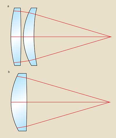
Figure 1. (a) Two-lens system with spheric lenses versus an equivalent system with a single aspheric lens. (b) The aspheric lens optimizes performance by converging to a diffraction-limited focused spot.
The first pitfall: Raytrace codes can generate shapes that are difficult to manufacture and/or test. The second: Cost and lead time of optics depend heavily on the manufacturing and testing techniques used to make them. Fortunately, optics designers can avoid these pitfalls by understanding the lens manufacturing process and by applying some simple constraints during design optimization.
Manufacturing of aspheric optics has grown dramatically in the past couple of decades. Many new options for both manufacturing and testing are now viable and even commonplace. When optimizing a design with an asphere, it’s crucial to be familiar with manufacturing options so that the design is properly constrained to be the most manufacturable while performance goals are achieved.
How aspheric lenses are made
Here’s how aspheric manufacturing differs from traditional spherical manufacturing: In traditional spherical manufacturing, the surface is defined by a single radius of curvature. That curvature can be ground and polished into the surface using large tools that work the entire aperture of the surface at once. The polishing tool will have the opposite curvature of the finished surface and, by oscillating about the center of curvature with a polishing medium such as slurry, the tool will smooth out the surface to the desired shape.
Aspheres are not defined by a single radius of curvature, so a single large tool will not match the desired surface as it oscillates over the surface (Figure 2). Therefore smaller subapertures are used, varying the radii of curvature at different points along the surface. Different manufacturing techniques address these subapertures in different ways, each resulting in its own advantages and disadvantages.
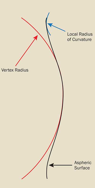
Figure 2. Local radius of curvature changes at different points on the aspheric surface, while the local radius of curvature at the center of the lens is defined as the vertex radius.
The computer numerically controlled (CNC) grinding and polishing process uses tools with a small contact area on the optic, and their position and the point about which they oscillate are guided under precise mechanical control.
Grinding is often done with ring tools – tilted, rotating rings that touch the optical surface only in a small area. Polishing is often done with a small but compliant polishing pad that conforms to the shape generated in the grinding stage.
Magnetorheological finishing (MRF) is a special polishing process used in conjunction with CNC grinding and polishing to provide even more control over the surface. In MRF, a ribbon of fluid is used to polish the surface. The ribbon changes viscosity in response to a varying magnetic field, so the removal rate can be precisely adjusted as the part is being polished, allowing for corrections even within the rotation of the part to correct any nonrotationally symmetric error on it. The process uses a wheel to pass a very small portion of the ribbon across the surface at any given time, allowing for correction of small areas.
Diamond turning is a similar small-tool option that uses a single-point tool to manufacture the surface. The tool is so minuscule that it removes material on the order of the surface roughness of the final surface specification; as such it does not require a separate polishing step.
All of these techniques are subtractive manufacturing methods, wherein material is removed to form the final surface. Alternatively, molding can be used to make surfaces without removing material.
Some economies of scale are possible with subtractive manufacturing methods, but the efficiencies of these methods are ultimately limited by the time needed for each step in the process. Molding offers significantly lower per-piece process times and expenses. Initial costs are high because tooling is expensive, so in low volumes it’s seldom economical; however, in mid to high volumes, the reduced per-piece costs outpace initial investment.
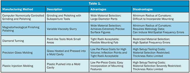
The two primary methods for molding optics are precision glass molding and plastic injection molding. In precision glass molding, glass is heated to its softening point and compressed between two molds with great force. In plastic injection molding, liquid plastic is forced into a mold and cooled to a solid.
Design features
Each fabrication method has its own unique strengths and limitations. If a design is optimized for the strengths of one manufacturing method (and to avoid that method’s limitations), it would likely be difficult to manufacture that design using another method. So, it is important to determine the best manufacturing method for a design prior to final optimization.
Material selection
CNC and MRF work well with optical glasses and crystalline materials; they do not, however, work on plastics. Diamond turning is suitable for crystals, plastics and many metals. Diamond turning works very well with materials used for IR optics, which are also less sensitive to the generally higher surface roughness inherent in diamond turning.
Precision glass molding is limited to glasses that have transition temperatures <500 °C and with sufficiently low coefficients of thermal expansion, resulting in a very limited selection of glasses. The choices have increased dramatically in the past decade but still represent only a fraction of all available optical glasses. The molding process takes glass from its softening temperature down to room temperature in a short amount of time, which anneals the glass and reduces its index. This drop means the finished optics will not have the same index as the catalog specification for the glass. When designing for precision glass molding, users need to account for this lower index in their models.
As the name suggests, plastic injection molding is limited to plastics, of which there are very few options.
Radii of curvature
Unlike spherical lenses, aspheric lenses do not have a single radius of curvature. The local radius of curvature varies from the center of the part to its edge. This leads to the possibility that the local radius of curvature can change its sign from convex to concave at different points on the surface, as illustrated in Figure 3. The point where this occurs is called an inflection point, and it can cause problems with tooling and measurements. Within Zemax software, the surface-curvature cross-section plot can be used to check the local radius of curvature on a surface. Examination of the plot reveals inflection points where the plot crosses the zero curvature, which can help predict tooling issues where the concave radii are too small.
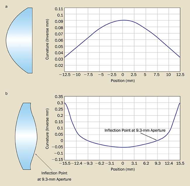
Figure 3. (a) If the aspheric lens has no inflection point, the curvature is never equal to zero. (b) When an aspheric surface has an inflection point, the inflection occurs where the curvature equals zero – in this example, at the 9.3-mm aperture.
The finite tool size in both CNC grinding and polishing and MRF polishing limits the concave radius of curvature that can be manufactured. The specific limitation varies depending on the tools, but it is typically between 10 and 20 mm for most machines. Inflection points are not necessarily a problem, but they can create a local curvature too small for the machine to handle. In addition, MRF requires detailed surface metrology prior to any finishing steps. The ideal metrology for this is stitching interferometry, which can’t measure a surface with an inflection. Diamond-turning tools are significantly smaller, and the minimum concave radius is typically on the order of millimeters for most tools.
Both precision glass molding and plastic injection molding are less restrictive with regard to local radii and surface geometries. Both can even allow for mounting features and other complex shapes; however, sharp corners will decrease tool lifetime and introduce surface errors near those transitions.
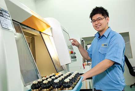
Figure 4. The manufacturing cell shown features state-of-the-art production and metrology equipment.
External dimensions
The shape of the aspheric element as a whole – its diameter, edge thickness and relative thickness across the part – will affect its manufacturability in different ways for different manufacturing methods.
The edge thickness for a small-tool-polished part is important, not only for strength to avoid edge chipping, but also to provide enough material beyond the nominal edge so the part can be polished to a larger diameter without running out of material. For CNC grinding and polishing, as well as MRF polishing, the part needs to be polished to a larger diameter. This accounts for the tool size, so the polishing tool doesn’t overhang from the surface during polishing (such an overhang can cause surface form errors).
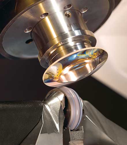
Figure 5. Testing and quality assurance on optics and optical assemblies can be customized to meet project requirements.
Typically a part needs to be about 5 mm larger than the necessary clear aperture during polishing. If edge thickness does not allow for the part to be that large, expensive and time-consuming tooling is required to avoid surface-form errors. The larger diameter is later reduced to final diameter in a centering step after polishing. Diamond turning does not require the oversized part because the tool size is so much smaller.
Spring factor – the ratio of the diameter of the element to its thickest point – also is a constraint in polishing. The larger this ratio, the more a part can flex when removed from the polishing fixture. CNC polishing is more affected by this than MRF. For CNC polishing, a spring factor of less than 8 is ideal if a tight surface figure is required, but that ratio can rise to 20 if looser surface figures are acceptable.
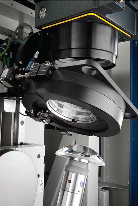
Figure 6. Stock optics can be customized by size, shape and edges, improving the surface figure or accuracy of the optical surface.
The molding process also constrains the largest thickness of the element because of limits on the cavity size for molding tooling, which can vary depending on the manufacturer. Furthermore, in precision glass molding, thickness affects heating and cooling times and will also drive the price of parts.
The ratio of maximum and minimum thickness of the part is also a restriction for molding. Both precision glass molding and injection molding require a ratio of 3 or less. Factors such as stress in the material, cooling rates and shrinkage result in the need to control thickness deviation across the element.
Diameter is seldom a restriction for polishing and diamond turning, at least until sizes exceed 150 mm, at which point the choice in manufacturers may become limited. However molding is far more restrictive, with both precision glass molding and plastic injection molding limited to maximum component diameters around 30 mm.
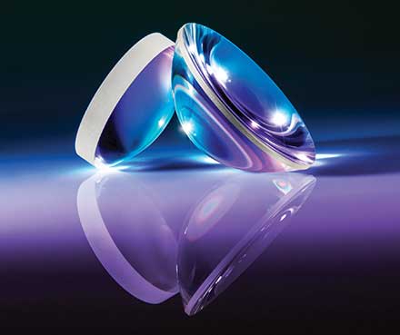
Figure 7. TechSpec® precision aspheric fused silica lenses are manufactured using precision grinding and polishing equipment.
Mounting design
Both plastic injection molding and diamond turning allow a lot of flexibility in the design of mounting features into the element. Precision glass molding has some flexibility but still restricts how sharp corners can be and how dramatic transitions in thickness can be. CNC grinding and polishing and MRF are limited to what can be done by removing material after the polishing or finishing steps – one example is grinding a flat annulus into the edge of a concave surface.
Surface accuracies
Each method of manufacturing is limited in how accurately it can achieve the designed surface shape. CNC polishing and precision glass molding achieve very similar surface accuracies. Diamond turning is also similar, but this method has more high-frequency errors or surface roughness. MRF gives superior surface accuracies but can have mid-spatial frequency errors. Plastic injection molding has the lowest surface accuracies of these methods.

Figure 8. TechSpec® laser-line coated precision aspheric lenses are designed to maximize performance in high-power Nd:YAG laser applications.
Design considerations
A quick review of each aspheric manufacturing method makes it clear that no single technique can satisfy every possible need. Working with a manufacturing partner, optics designers can select the method that matches their primary requirements, then evaluate the design for minor changes that can drastically improve manufacturability of the part. In this way, designers can tune their material selection – general surface profile and mounting design, for example – to fit the fabrication method required to meet the part’s diameter and thickness specifications.
This is only the beginning, however. Detailed design specifications can be tuned to ease both fabrication and metrology, thereby optimizing manufacturability. The second article on this topic will discuss those details.
Images courtesy of Edmund Optics