Full company details
CoolLED Ltd.
 26 Focus Way
Andover, Hants SP10 5NY
United Kingdom
Phone: +44 1264 323040
Fax: +44 1264 723897
Toll-free: +1 800-877-0128
LEDs and Optical Filters Expand Live-Cell Imaging Capability
BioPhotonics
Mar/Apr 2022The proper illumination system can provide the best wavelength specificity, speed, and contrast for each microscopy experiment while reducing the phototoxicity that could damage a sample.Isabel Goodhand, CoolLED
The light source of a wide-field fluorescence microscope is often overlooked by scientists who perform live-cell imaging experiments. However, innovations such as transistor-transistor logic (TTL) triggering, which enhances on/off speed, and inline excitation filters that allow for fast imaging in specific wavelengths have elevated this component. What was once a basic illuminator has become a highly controllable system with the potential to advance fluorescence microscopy.
Unlike traditional mercury and metal halide lamps, LED illumination systems are solid-state, offering an extra level of electronic control and discrete spectra. By moving away from white-light illumination, which is not wavelength-specific and can cause phototoxicity and photobleaching, LED illumination technology opens up opportunities to enhance three key aspects of live-cell imaging: speed, phototoxicity, and contrast.
Speed
High-speed imaging is the key to capturing dynamic events in detail at the cellular and molecular level. An increase in temporal solution also increases the accuracy of measurements when applying ratiometric fluorescence techniques such as Fura-2 calcium imaging, which can measure the activity of countless neurons simultaneously (Figure 1). For imaging multiple fluorophores, using a traditional white-light source requires the use of expensive motorized equipment, such as filter wheels that have limited ability to capture the desired data for high-speed events. However, LED innovations provide a faster and more cost-effective approach.

Figure 1. A rabbit brain with fluorophores illuminated by LEDs. Courtesy of CoolLED.
Phototoxicity
Biological samples that are exposed to high-intensity light can trigger the release of reactive oxygen species, causing damage to DNA and proteins. This fundamental challenge to the use of fluorescence microscopy in the life sciences is concerning not only in terms of cell viability, but also in terms of cell health — that is, whether cells exhibit their natural behavior. Research reveals how phototoxicity can subtly alter a cell’s physiology, which can create misleading experimental results that compromise the accuracy of the information presented
1,2.
Another impact of illumination is photobleaching, where the fluorophore is transiently altered into a dark, nonfluorescing state that compromises the integrity of the image. Alternatively, atoms existing in the dangerous triplet state can absorb enough energy created by the light source to break covalent bonds and irreversibly damage the chemical structure, destroying the cell’s viability for further study. The speed of photobleaching varies between fluorophores and can result in data misinterpretation. The question arises: Does signal loss occur due to the biology or to the photobleaching? Time-lapse experiments also become limited as signal fades. Carefully optimizing the light exposure to all biological samples is therefore crucial for accurate data.
Contrast
Increasing the signal-to-noise ratio (SNR) of live-cell images can reveal more information that will help to answer the biological question under investigation. Image contrast can be enhanced to improve SNR by exposing the sample only to the wavelengths that are required to excite the fluorophores in use.
LED innovations
To increase imaging speed and contrast while also minimizing phototoxicity, LED illumination has evolved to incorporate several features.
Individual channel control. No optical filter that is incorporated into an illumination system can provide a complete barrier to unwanted wavelengths. Therefore, white-light sources transmit a level of background noise that impedes the imaging process, reducing the SNR and impairing contrast. To enhance contrast, many LED illumination systems offer the ability to apply only the wavelengths required to excite specific fluorophores.
Moreover, white light from traditional lamps tends to have a higher irradiance in the higher-energy UV region of the spectrum, which poses a far greater risk of phototoxicity compared to the longer-wavelength, lower-energy red regions. LED illumination systems offer far more choice in excitation wavelengths — extending to 850 nm. New fluorophores that are excited by these longer wavelengths are becoming available all the time, alongside the optical filters that enhance their usability in imaging.
TTL for speed. Physical shuttering with traditional lamps can introduce latencies of up to 20 ms for each exposure
3, whereas the electronic control of LED illumination is significantly faster between exposures. A popular approach is to operate LED illumination systems using imaging software in which aspects such as the illumination wavelength channel and irradiance can be optimized with ease. However, latencies in response time can be introduced by USB serial communications and computer operating system overheads, slowing LED on/off speeds by as much as 100 ms.
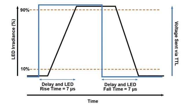
To remove this variable latency, digital control via TTL pulses can consistently achieve LED triggering speeds of <7 µs (Figure 2). This often relies on a special USB-controlled TTL trigger box, which allows software settings to run via high-speed TTL signals. Alternatively, some light sources allow a camera (or other hardware) with a TTL output port to be connected directly to the light source and controlled using a sequence runner function, eliminating the cost and complexity of specialist equipment. This is a simplified approach to TTL control, where the user can select a sequence via manual control or software, which will cycle through as each TTL signal triggers the next LED in the sequence.

Figure 2. A transistor-transistor logic (TTL) control for high-speed imaging. Pulses of 5 V (blue line)
from hardware such as microscope cameras or USB-controlled TTL trigger boxes can be used to control one or all channels of an LED illumination system. This enables LEDs to be triggered at speeds of <7 µs (black line), which is significantly faster than relying on physical shuttering or PC operating systems. Courtesy of CoolLED.
Inline excitation filters. A common misconception in multicolor fluorescence imaging is that a trade-off must be made between speed and contrast, with the choice being between single-band filter cubes mounted into a motorized filter cube turret, which offers high contrast but low speeds, and multiband filter sets, which offer high speeds but low contrast.
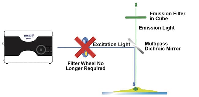
While this trade-off is necessary for white-light systems, many LED illumination systems can combine individual channel switching with the ability to fit excitation filters in the LED illumination system itself, in front of each individual LED channel. This option allows the best of both worlds when used with Pinkel filter configurations, which include single-band excitation filters alongside a multiband emission filter and a multiband dichroic mirror. Because the single-band excitation filters are housed within the illumination system, and the filter cube that contains the multiband dichroic mirror and emission filters remains stationary, this removes mechanical latency from the system’s operation (Figure 3). The speed of the illumination system is then limited only by LED channel switching.

Figure 3. A high-speed, cost-effective alternative to filter wheels. To fully capitalize on electronic
LED switching speeds for multilabel imaging, latency from mechanical movement is avoided by utilizing individual LED channel switching and a Pinkel optical filter configuration. Single-band excitation filters
are housed within the LED illumination system, while the filter cube houses a multiband dichroic and
emission filter. Courtesy of CoolLED.
For example, consider an LED illumination system that includes inline excitation filter holders loaded with a quad-band Pinkel filter set, along with individual channel control and high-speed TTL triggering. In this setup, a fluorescence microscopy experiment can potentially image cellular activity using fluorophores — such as DAPI, FITC, TRITC, and Cy5 — at speeds limited only by the TTL triggering (or other components, such as the camera). And, as previously mentioned, these speeds can be as fast as <7 µs.
Selecting optical filters
In addition to optical filter configuration, the specifications of the filters themselves can affect the usability of the data gained from a fluorescence microscopy experiment. Filters that are optimized for a defined set of fluorophores will expose the sample only to the most suitable wavelengths, maximizing the SNR and leading to brighter and higher-contrast images, which is essential for single-molecule localization or in medical diagnosis. Selecting optical filters is even more important when using multiband filters, which must be chosen carefully to avoid bleed-through (also known as crosstalk or signal interference) and a reduction in the SNR. However, the filters must be optimized for use with the specific light source as well as the targeted fluorophore.
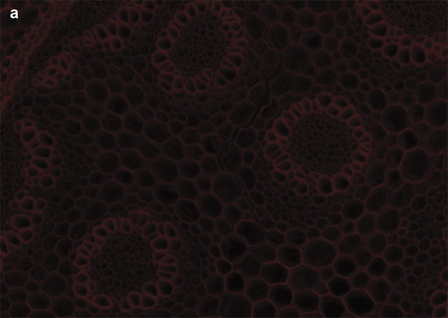
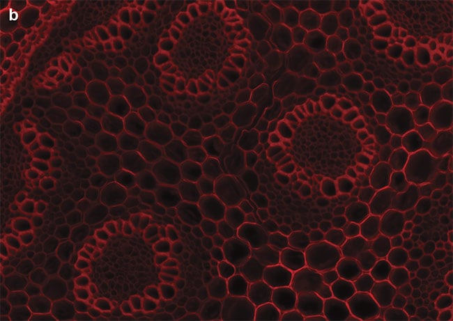
Optical filters have historically been designed for mercury and metal halide lamps, capturing light around the regions of their spectral peaks. LED illumination — with its discrete spectra — instead requires optical filters that cover the common LED wavelengths. Optical filter manufacturers now supply researchers and scientists with filter sets matched to the spectra of LEDs and popular fluorophores. When used with LED illumination systems, these optimized filter sets increase the SNR and minimize bleed-through to enhance multicolor imaging. An example can be seen in Figure 4.


Figure 4. Sample images of autofluorescence in Convollaria (Lily of the Valley). LED-optimized filters enhance contrast, and optical filter sets must be chosen carefully to maximize the image contrast. Standard filter sets, such as the Chroma ET49008, are designed to capture photons from peaks of mercury or metal halide lamps (a). New filter sets, such as the Chroma ET49055, are instead optimized around peaks of LED wavelengths (b). Courtesy of CoolLED.
Determining the spectral data that maximizes the relationship between optical filters, LEDs, and fluorophores can be complex, but online tools are available. These include tools for visualization, such as FPbase.org, and those available from light source and filter manufacturers.
Looking forward
Light sources for fluorescence microscopy have come a long way from the basic lamps that provide indiscriminate white lighting. Since LED illumination systems became commercially available in 2006, electronic control has opened up new avenues for their use in high-performance live-cell imaging using wide-field microscopy.
As more spinning-disk systems emerge in the market, newer and even brighter LEDs are becoming an increasingly viable alternative to lasers in live-cell imaging scenarios, overcoming the cost and safety challenges of powerful multiwavelength control. It is now more important than ever to keep up to date with the latest developments in order to make the most of TTL control and Pinkel filter configurations that use optimized filter technology.
Meet the author
Isabel Goodhand, Ph.D., technical content specialist at CoolLED, completed her doctorate in 2011 at the University of Portsmouth in England, where she developed a method to quantify protein-DNA binding activity. After leaving academia, she has since specialized in scientific communications across the science and engineering sectors. She joined CoolLED in 2019 and helps to keep the microscopy community up to date with the latest developments in LED microscopy illumination.
References
1. M. Jemielita et al. (2013). Comparing phototoxicity during the development of a zebrafish craniofacial bone using confocal and light sheet fluorescence microscopy techniques.
J Biophotonics, Vol. 6, Nos. 11-12, pp. 920-928,
www.doi.org/10.1002/jbio.201200144.
2. J. Icha et al. (2017). Phototoxicity in live fluorescence microscopy, and how to avoid it.
BioEssays, Vol. 39,
www.doi.org/10.1002/bies.201700003.
3. A. Kiepas et al. (2020). Optimizing live-cell fluorescence imaging conditions to minimize phototoxicity.
J Cell Sci, Vol. 133, No. 4, jcs242834,
www.doi.org/10.1242/jcs.242834.