Full company details
Applied Scientific Instrumentation Inc.
 29391 W Enid Rd.
Eugene, OR 97402
United States
Phone: +1 541-461-8181
Fax: +1 541-461-4018
Toll-free: +1 800-706-2284
Light Sheet Microscopy: Transforming 3D Fluorescence Imaging
BioPhotonics
May/Jun 2020Selective plane illumination microscopy opens new avenues in biomedical research.JON DANIELS, APPLIED SCIENTIFIC INSTRUMENTATION INC. (ASI)
Light sheet fluorescence microscopy (LSFM) is a fast and efficient imaging technique that combines the speed of wide-field imaging with optical sectioning and low photobleaching. LSFM has become an important fluorescence imaging modality, especially for volumetric (3D) imaging. Prominent applications include developmental biology, cleared tissue imaging, cell biology, and neuroscience.
Selective plane illumination microscopy (SPIM) initially referred to a specific form of LSFM, but SPIM has become synonymous with LSFM. “Light sheet microscopy” is also a synonym because nearly all light sheet imaging utilizes fluorescence. The terms LSFM, SPIM, and light sheet microscopy will be used interchangeably here.
The concept of selective illumination was first implemented in the early 1900s, rediscovered in the context of fluorescence microscopy in the 1990s and early 2000s, and widely adopted during the last decade. Initial applications in the 1990s leveraged the gentle characteristics of SPIM for long-term imaging of developing organisms. The technique has since spread to applications in which imaging speed and throughput are important, including imaging dynamic phenomena and large samples that have been rendered transparent by chemical clearing.
Fluorescence microscopy is an important technique for biomedical research because the underlying mechanism is highly selective, meaning that the resulting image shows only the fluorophores (fluorescent molecules) and not everything else around them. For example, biological processes can be elucidated by time-lapse microscopy of model organisms (such as worms, flies, or fish) in which cells have been genetically modified to express fluorescent proteins at predetermined locations and/or under specific conditions.
In fluorescence microscopy, the specimen or sample is illuminated with photons of light of a specific wavelength. Fluorophores can absorb these photons and reemit them as photons with less energy (longer wavelength), and a microscope image is formed based on the location and amount of reemitted light. The illumination light can damage the fluorophores and/or disrupt natural processes in living specimens, so it is beneficial to use the illumination light efficiently.
Advantages of the light sheet
The defining feature of SPIM is the placement of illumination or fluorescence excitation light in the (micron-thin) focal plane of the detection objective lens (Figure 1). In conventional fluorescence microscopy, including wide-field epifluorescence and confocal microscopy, the entire thickness of the sample is illuminated from the same direction as the detection optics, meaning that regions outside the detection objective’s focal plane are potentially damaged by the wasteful illumination light. Furthermore, fluorescent photons arising outside the focal plane degrade the image quality. In contrast, in light sheet microscopy, the sample is illuminated from the side, usually 90° from the direction of observation, so that the excitation light is placed only where it is needed. Figure 2 shows a simplified light sheet microscope.
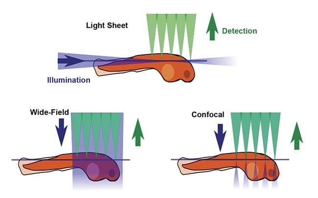
Figure 1. A comparison of fluorescence microscopy illumination methods. Courtesy of JKrieger/CC BY-SA 3.0/Modified from original.
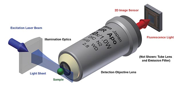
Figure 2. A conceptual overview of a light sheet fluorescent microscope. Courtesy of JKrieger/CC BY-SA 3.0/Modified from original.
Light sheet microscopy has rapidly gained popularity due to the following features, which all arise because of selective illumination:
1. Photodamage is minimized. Less total excitation light is needed to create each image, so there is less damage to the fluorophores, and living specimens stay alive for much longer.
2. Good optical sectioning is obtained. In other words, contrast is improved. Because excitation occurs only near the focal plane of the detection objective, the amount of out-of-focus fluorescence is minimized. Confocal microscopy achieves optical sectioning by different means, but it illuminates the entire thickness of the sample and therefore causes more photodamage.
3. Imaging speed is orders of magnitude faster than with confocal scanning microscopy because an entire 2D plane is imaged simultaneously, typically with an sCMOS image sensor. This is called wide-field detection.
These significant benefits of selective illumination come at the cost of a more complicated microscope. The optimal place to add complexity depends upon the imaging requirements, often specific to the type of specimen. As a result, many different light sheet microscope configurations have been developed, each based on similar principles but with their own advantages and disadvantages for particular types of samples. By understanding the underlying principles behind light sheet microscopy, readers will be better equipped to navigate the bewildering array of configurations to identify the ones best suited for their research.
How the microscope works
To implement selective illumination microscopy, a light sheet needs to be generated and introduced at the sample. Multiple fluorescence images are taken at various positions to build up a 3D representation of the specimen.
Static or scanned light sheet
There are two primary approaches for generating a sheet of light (Figure 3). A cylindrical lens or similar element can focus the illumination light in one axis to give a thin sheet while the light remains distributed in the other axis (the sheet width), thus illuminating the entire detection field of view all at once. This is commonly referred to as a “static” sheet. The other method forms a sheet by quickly scanning a focused beam of light across the field during each camera exposure, which is called a “scanned” or “virtual” sheet.
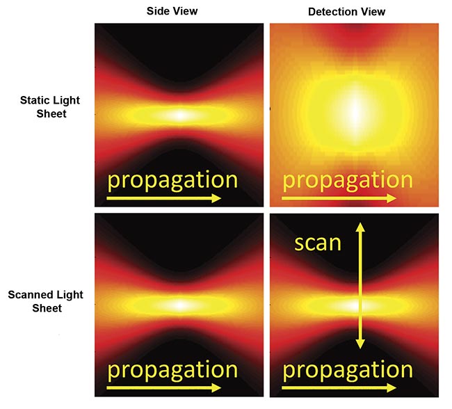
Figure 3. Instantaneous illumination intensity for static (top) and scanned (bottom) Gaussian light sheets as seen from the side and from the detection objective. The illumination optics would be to the left side. Courtesy of ASI.
Static sheets are easier to generate and have lower peak illumination intensity, which often reduces photodamage. Because of the details of the sCMOS camera readout, static sheets can usually attain faster imaging speeds than scanned sheets. However, static sheets generally have spatially uneven illumination intensity due to the source’s origin as a Gaussian beam. Scanned sheets provide uniform illumination over an easily changed width, have a “stop motion” effect that eliminates motion artifacts in moving samples, and can be combined with a camera’s rolling shutter to improve contrast.
Sheet profile
An ideal light sheet would be extremely thin, with intensity completely confined to the focal plane of the detection objective, and would be long enough to cover the entire field of view of the detection objective. Achieving this ideal is not possible because focused light diverges. The sheet length is defined as the distance along the illumination light’s propagation direction, over which the sheet is relatively thin (and has relatively uniform thinness) before it diverges. The thinness and length of the sheet are mathematically related; halving the thinness results in a sheet only a quarter as long.
For the most common and easily generated light sheet type — Gaussian — the thinness and length are both controlled by a single parameter, NAill, as shown in Figure 4. In practice, the sheet length is usually chosen to match the size of the specimen (or the detection objective’s field of view), which fixes the sheet thinness. Figure 5 gives exemplary values for sheet thinness and corresponding lengths for Gaussian sheets.
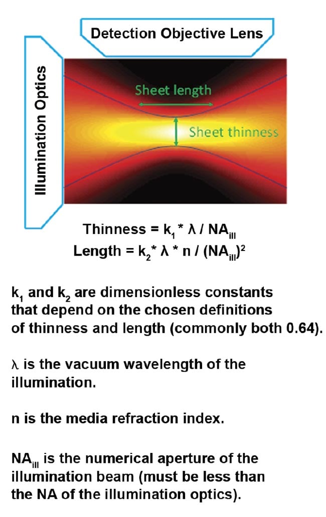
Figure 4. The intensity of a focused Gaussian beam or sheet and the corresponding equations for thinness and length. Courtesy of ASI.

Figure 5. Sheet thinness and lengths of Gaussian light sheets for representative NAill values. Assumes 488-nm excitation in water and uses the most common thresholds for defining thinness and length.
Various non-Gaussian beam profiles have been employed for light sheet microscopy, including Bessel, Airy, and optical lattices. One advantage of using these sheet profiles is that the sheet length can be several times longer than a Gaussian one for the same thinness. However, using non-Gaussian sheets often adds significant complexity (and cost) to the microscope compared to easily generated Gaussian sheets. The quadratic trade-off between sheet length and thinness holds for all types of sheets, just with a different prefactor.
The thinness of the sheet can be quantified by two metrics — either the thinness of the central lobe (which affects axial resolution) or the thinness of the region containing the majority of the light (which affects optical sectioning). For example, Bessel beams have thin central lobes but lots of light outside the central lobe, meaning they appear as thin beams from the standpoint of axial resolution but as thick beams from the standpoint of optical sectioning or image contrast. Gaussian beams have excellent performance in terms of optical sectioning.
Introducing the light sheet at the sample
The way the light sheet is introduced usually restricts the ways the specimen can be mounted in the microscope. A common method is using an illumination objective lens placed orthogonal to the detection objective lens. In other words, two objective lenses are near the sample, resulting in geometric constraints. For example, two objective lenses can be in a horizontal plane, with the specimen lowered between them, or else two objectives can each be at 45° from vertical and lowered into an open dish containing the specimen. In some situations, simple lenses are sufficient instead of an illumination objective to generate the light sheet.
It is also possible to introduce the illumination from the same objective lens used for detection. However, such a sheet cannot be coincident with the detection objective’s focal plane because objective lenses have less than a 90° optical half-angle. Two methods have been developed to work around this limitation. In one, a mirror is added to the side of the sample and used to reflect the illumination light so that it becomes orthogonal to the objective’s optical axis. In the other, a tilted sheet is introduced at the sample and then a specially constructed optical relay creates a remote replica 3D image of the sample and light sheet, where another objective lens is placed with matching tilt.
Volumetric imaging
To collect volumetric (3D) information, a series of images — usually called an image stack — is collected as the light sheet is moved relative to the sample. Sheet scanning moves the light sheet and the focal plane of the detection objective while the sample remains stationary. In contrast, sample scanning involves moving the sample through a stationary light sheet. In either case, the camera speed and/or sample brightness limit how fast each image can be collected. When repeatedly reimaging the same 3D volume for studying dynamic phenomena, care must be taken to select hardware that can quickly return to its initial position.
Some single-objective light sheet configurations move the light sheet and imaging plane together using a galvo mirror, which simultaneously scans the light sheet illumination and descans the emission image (like in confocal scanning microscopy, except it scans one plane at a time instead of one point at a time).
LSFM generates image data at a tremendous rate, commonly in the range of 5 to 500 images per second, depending on the camera, image size, and sample brightness. This speed is a major advantage of light sheet microscopy compared with confocal scanning microscopy, but it requires consideration of data handling requirements for both acquisition and post-processing.
Optical resolution
The detection objective lens’ numerical aperture is the critical parameter in determining achievable resolution, and increasing the detection NA also results in more photons being collected. There are two types of resolution to consider. Lateral resolution is the ability to distinguish nearby features within the same focal plane (or 2D image), whereas axial resolution is the ability to distinguish features in different focal planes, analogous to depth perception. Both types are expressed as the distance at which nearby objects begin to be indistinguishable, so lower numbers correspond to sharper images and are therefore preferred.
Figure 6 shows the diffraction-limited lateral and axial resolutions for wide-field detection for representative NA values. Note that axial resolution is significantly worse than lateral due to the physics of light. Selective illumination improves axial resolution beyond the wide-field case, sometimes slightly and sometimes significantly. Selective illumination can be combined with superresolution microscopy techniques to further improve resolution.

Figure 6. Lateral and axial resolution for various values of wide-field detection numerical aperture (NAdet) values. Assumes 510-nm emission in water and uses the most common thresholds for defining resolution. Note that the use of LSFM often improves axial resolution.
The optical sectioning inherent in SPIM improves image contrast compared with wide-field illumination. Furthermore, selective illumination improves the diffraction-limited axial resolution to the extent that the light sheet is thin compared to the objective’s intrinsic axial resolution. Mathematically, the overall axial resolution results from multiplying the point spread functions of the excitation and detection, and whichever is smaller will become the main determinant of the combined axial resolution.
When the detection NA is low, the wide-field axial resolution is so large that generating a light sheet thin enough to improve upon the resolution is straightforward, but the improved resolution is usually still poor compared to lateral resolution. For example, with an NA 0.2 detection objective, the wide-field axial resolution is 34 µm. For a Gaussian sheet 1 mm long, the sheet is 16 µm thick, resulting in combined axial resolution of about 11 µm, which represents a three-fold improvement in original axial resolution but is still sevenfold worse than the lateral resolution.
With high-NA-detection objectives, however, it is difficult to generate sheets thinner than the native axial resolution over a practically large field of view. For example, with an NA 1.0 detection objective lens, the wide-field axial resolution is 1.4 µm, and generating a Gaussian sheet with comparable thinness results in a sheet length of less than 8 µm. To achieve a more reasonable 85-µm sheet length, the light sheet thinness is 4.5 µm, or several times thicker than the objective’s focal plane. In this example, the axial resolution is essentially the same as wide-field detection, but optical sectioning improves image contrast compared to wide-field illumination. Computational deconvolution can further improve image quality because part of the light sheet is out of focus (i.e., the optical sectioning is imperfect).
If the specimen is imaged from various vantage points, individual data sets can be combined into a single 3D data set with improved resolution. For example, if two image stacks of the same sample region are collected from orthogonal directions, each stack’s (low-resolution) axial direction corresponds to a (high-resolution) lateral direction in the other stack. Intelligent computational fusion of the two stacks results in a 3D data set with “lateral” resolution in all directions. Besides improving resolution, such multiview approaches are required in some applications to see all sides of an opaque or scattering specimen.
Dealing with scattering
Scattering specimens present difficulties on both the illumination and detection paths.
On the illumination path, opaque regions in the sample block the light sheet and lead to stripe artifacts in images, caused by shadows in the illumination light. Shadowing can be mitigated through several strategies. The classic “anti-striping” approach pivots the light sheet within the same plane to reduce shadows. Other systems use multiple light sheets coming from various directions.
Scattering of emitted fluorescent
photons blurs the resulting image. Many sCMOS cameras offer a light sheet readout mode that can be combined with scanned sheet illumination to reject scattered and out-of-focus light in the scan direction. In this method, only a few contiguous rows of the camera are active at a time, acting like a slit that moves across the camera sensor during the exposure time. This technique requires excellent synchronization between the scanned beam and the camera, and cannot be combined with static sheet generation or anti-striping. A closely related technique called axially swept light-sheet microscopy, which is a hybrid between line scanning confocal microscopy and SPIM, achieves optical sectioning with intermediate illumination efficiency.
Choosing the best configuration
There are dozens of possible configurations for light sheet microscopes, depending on sample mounting, objective lens configuration, type of light sheet, adaptations for scattering, and so on. Each configuration has its own advantages and disadvantages for various types of samples. Many configurations are known by initialisms with no consistent nomenclature. The myriad configurations and names can be bewildering for newcomers, but those who understand the fundamental principles and considerations underlying SPIM are empowered to obtain and fully utilize a microscope tailored to their experimental needs.
When trying to decide on the optimal LSFM configuration for a particular application, start by answering the following four questions:
1. What is the required spatial resolution (laterally and axially)?
2. What is the required temporal resolution or acquisition speed?
3. What are the constraints on sample mounting/handling?
4. What are the dimensions of the 3D volume to be imaged?
The required lateral dimensions and spatial resolution will dictate the choice of detection objective. The imaging speed requirement affects the choice of motion control. The time required for camera readout limits the attainable acquisition speed for bright samples; for dim samples, the exposure times must be longer to collect enough photons. Sample mounting plays into the choice of objective geometry and is usually a significant practical concern. The dimensions of the imaged volume will affect choice of motion control as well as light sheet thinness.
Light sheet fluorescence microscopy (or equivalently, LSFM or SPIM) in its multitude of forms is becoming increasingly popular due to its combination of speed, photon efficiency, and optical sectioning. There are various commercial offerings of many LSFM configurations at different levels of capability and expense. Many microscopy experts expect that light sheet will gradually replace confocal as the most common fluorescence microscope modality. Understanding the underlying concepts of SPIM enables potential users to select a variation that best fits their needs.
Meet the author
Jon Daniels, Ph.D., is a scientist, engineer, and jack-of-all-trades at Applied Scientific Instrumentation Inc. (ASI). His formal education is in physics, chemistry, and electrical engineering. He discovered a passion for developing scientific instruments during his doctoral studies, and light sheet microscopy is his most recent focus.
Acknowledgment
Significant improvements to this article were suggested by colleague Melissa Glidewell.