Mechanical vibration, moving parts and turbulent airflow present significant problems for most interferometric test methods. New techniques help solve the problem.
John Hayes and James Millerd, 4D Technology Corporation
Conditions on the factory floor and in industrial cleanrooms with high-capacity air filtration systems can hamper the use of interferometry. Another problem is the testing of large-aperture mirrors where it is difficult to mechanically isolate them and the structures needed to support the optical test; in addition, long optical paths produce air turbulence problems.
To make things worse, the next generation of large-aperture lightweight mirrors for space-telescope applications must be tested in vacuum chambers at cryogenic temperatures where vibration is virtually impossible to control. The newer dynamic interferometers help solve these problems with even better accuracy than traditional temporal phase shifting interferometers.
A standard phase shifting interferometer (PSI) makes a measurement by introducing known phase shifts between the signal and reference beams and recording multiple sequential interferograms taken over time. Most commercial PSI systems incorporate a video camera that operates at 30 fps with an exposure time of about 30 ms. At this speed, a typical 5-frame algorithm requires at least 167 ms to acquire a full data set. This is not a particularly fast rate compared with typical mechanical vibrations. Not only can vibration blur the fringe signal during each 30-ms exposure; but the fringe pattern may also change significantly between exposures.
In its simplest form, minor vibration can cause errors that mimic calibration and nonlinear phase shifting errors. Because this type of error is dependent on the input phase of the signal, the result is a cosinusoidal error that follows the intensity contours of the base fringe pattern. Hence, this type of error is often referred to as print-through because the fringe pattern appears to print through into the map of the measured wavefront. These errors must be reduced if accuracy is to be achieved in a real-world environment where air turbulence and vibration cannot be eliminated.
The most common method of combating print-through errors in a PSI measurement is to take more frames of data over a larger period of time. The most basic algorithm requires a minimum of three measurements to compute phase and it is the most susceptible to print-through errors. There are numerous algorithms that use 4, 5, 8, 9, 11, 13 or even 20 frames of data. The primary limitation is how much phase change the phase shifter can introduce into the reference beam before it runs out of range. Although these algorithms help reduce print-through errors, none are perfect, and in the case of large amounts of vibration, this approach will simply not work at all. Figure 1 shows how 12 measurements can be averaged to reduce print-through errors.
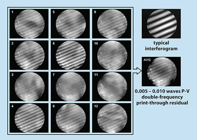
Figure 1. Print-through errors are measured on a temporal phase shifting interferometer with a 5-frame PSI algorithm for 12 data sets. The data was taken on a fairly stable table with only very small amounts of mechanical vibration. Tilt has been removed from each wavefront map to make the print-through more easily visible. Note that the amplitude of the print-through varies with each data set, decreasing the effectiveness of signal averaging.
Instantaneous interferometry
Fortunately, there are many ways to make interferometric measurements in the presence of a rapidly changing signal. The most effective is to take all of the data in a time period that is shorter than the time it takes for the signal to change very much. The first concept for a high-speed interferometer was suggested by Smythe and Moore in 1984. Dubbed a simultaneous phase shifting interferometer (SPSI), it used three or four separate cameras aligned with polarization beamsplitters to produce a co-aligned, phase-shifted image on each camera.
Phase shifting was achieved by orthogonally polarizing the reference and signal beams and using wave plates to introduce the desired phase shifts between channels.
The challenge for this system was achieving and maintaining subpixel mechanical alignment between the four cameras over the entire image. This requires six degrees of freedom for all four cameras with submicron resolution and stability. Coupled with multiple frame grabbers and timing circuitry, the commercial versions of the SPSI can grab all of the data needed to compute optical phase in a single 30-ms exposure. This arrangement eliminates the possibility of the signal changing between phase shifts.
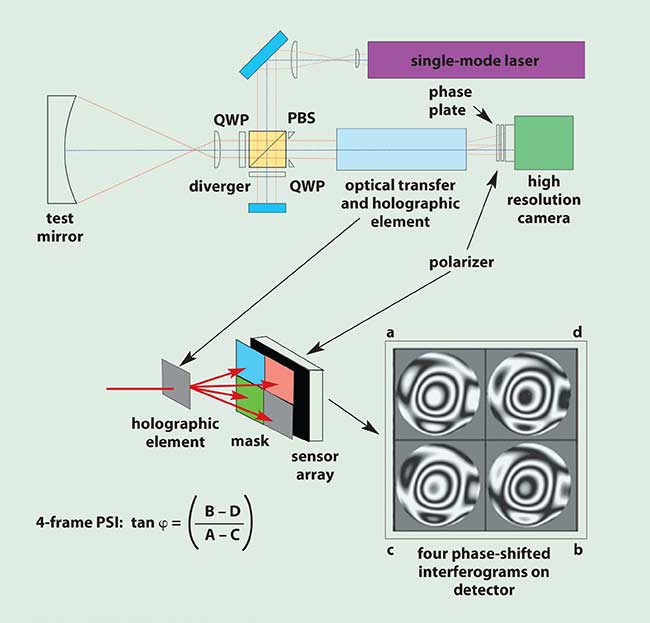
Figure 2. Operation of the 4D Technology quadrant sensor.
Probably the first practical commercial instantaneous interferometer was the Zeiss Direct 100 introduced in the early 1990s. The Direct 100 used a modified Fizeau configuration where the reference beam could be significantly tilted with respect to the test beam to produce very high spatial frequency fringes on a single detector. By carefully controlling the reference tilt to match the sampling period of the imaging camera, it used a technique called spatial carrier phase shifting to compute optical phase. This system acquired data in a few milliseconds, significantly improving vibration immunity.
Dynamic Interferometry
While instantaneous interferometers can make measurements in the presence of normal vibration, dynamic interferometers can make single-frame phase measurements with short exposures and create movies of phase changes. Early models of the 4D Technology PhaseCam Twyman-Green interferometers use a quadrant phase sensor to make high-speed interferometric measurements. The quadrant sensor uses a holographic element to split the image of the pupil into four quadrants of a high-resolution sensor as shown in Figure 2. By splitting the signal and reference beams into orthogonal polarizations, appropriate wave plates placed over each quadrant of the sensor introduce the phase shifts needed to compute optical phase. Exposure times in the range of tens of microseconds can be used to completely freeze the moving interference pattern even when the pattern is changing quite rapidly.
4D Technology has recently introduced a number of interferometers based on a completely new single-camera, polarization-based pixelated phase sensor. The sensor uses a single quarter-wave plate to circularly polarize the signal and reference beams and a pixelated polarization mask mounted in close proximity to the CCD sensor (Figure 3). To understand the sensor’s operation, it is instructive to think in terms of a standard RGB color sensor. These use three distinct sensors to detect red, green and blue levels for each supercolor pixel in an image. The pixelated phase sensor can be thought of in much the same way. In this case, a superphase pixel is composed of four pixels that sense 0°, 90°, 180° and 270° phase shift information. A standard 4-bucket phase algorithm can then be used to compute the phase at each superpixel location. In practice, the arrangement of pixels allows phase to be computed using a convolution process so that an N × N sensor yields an N - 1 × N - 1 array of data. Both four- and five-frame algorithms can be implemented by appropriate selection of the convolution kernel. The difficulties of making this type of sensor are reduced to producing the mask and mounting it on top of the CCD sensor. Once made, the phase camera is compact and robust. This sensor can be used over a range of wavelengths and is common path so that it is unnecessary to introduce large amounts of tilt between the reference and signal beams.
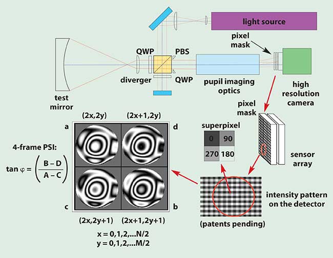
Figure 3. Operation of the 4D Technology pixelated optical phase sensor.
Signal averaging
In the presence of vibration, most commercial temporal PSI systems are often unable to make measurements. This inability to get good data makes signal averaging difficult. One advantage of single-sensor phase sensing is that data is almost never lost to vibration so that robust signal averaging can be performed. As we shall see, signal averaging is a very powerful advantage of dynamic interferometry.
One of the first advantages of signal averaging is the ability to reduce systematic errors. At first glance, it might seem possible to construct a single-camera polarization-based phase sensor to completely (or nearly completely) eliminate print-through errors — even with three or four data buckets. Unfortunately, this is not the case. Small errors in polarization optics or component alignments mean that print-through errors cannot be completely eliminated. Typical residual print-through errors in most dynamic phase sensors run in the range of 0.005 to 0.020 waves P-V.
This might seem like a problem since the sensor is restricted to a fixed number of phase buckets. Fortunately, there is a solution. Because the print-through errors are dependent on the phase of the input beam, averaging can reduce or eliminate these errors. It is important to understand that for averaging to work, the input phase must change — it cannot be stable; it must be vibrating. If the instrument must be used in a stable environment, a simple PZT phase shifter can be used to change the starting phase.
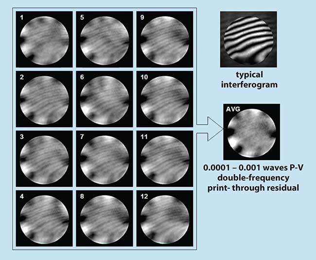
Figure 4. Print-through error is measured and averaged with a 4D Technology PhaseCam dynamic interferometer using 12 data sets. The individual phase maps have had the best fit 36 Zernike terms removed in order to make the print-through error visible under the base shape of the wavefront. The resulting print-through error in the averaged data is almost undetectable.
Because the print-through errors are periodic with nearly constant amplitude, it does not take very many frames to see improvements. Using between 8 and 16 frames is generally effective. This is roughly the same amount of data that must be acquired using standard temporal techniques. Therefore, there is virtually no speed difference between the two methods when making a high-accuracy measurement. Figure 4 shows an example using 12 frames.
Averaging to reduce air movement
Another advantage to signal averaging is that the effects of air turbulence can be greatly reduced. Vibration insensitive metrology is typically required for performing long path measurements. Over path lengths of tens of meters, air turbulence can introduce anywhere from 0.2 to 2.0 fringes of wavefront distortion that varies in a random way over the test pupil. By averaging over a period longer than the coherence time of the air turbulence, it is possible to greatly reduce the effects of turbulence. The amount of reduction is simply a matter of how much data is averaged:

where εTurb = the rms error contribution due to turbulence in the averaged result, RMSTurb = the rms error contribution due to turbulence in each measurement, and N = the number of measurements.
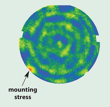
Figure 5. Surface deformation is due to mounting stress on an 18-in. diameter mirror measured by a PhaseCam over a turbulent roundtrip air-path of about 15 m. The stressed area is only about 10 nm above the surrounding region.
An obvious question is how much time is needed to take the data. It turns out that with a typical PhaseCam interferometer, averaging a couple hundred frames to remove air turbulence only takes a few minutes. At this rate it is possible to accurately map surface features of a few hundredths of a wave in height even with a round trip air path of 20 m. When averaging out air turbulence, it is effective to stir the air with a fan to reduce the coherence time and randomize the flow. Again, a dynamic interferometer gives a better result using signal averaging with more turbulence — not less. Figure 5 shows low-level mirror mounting stress after averaging out significant air turbulence over a long air path.
Measuring moving parts
Dynamic interferometers such as our PhaseCam and FizCam Fizeau interferometers provide sufficient speed to measure moving and vibrating parts accurately. By synchronizing data acquisition with a part being excited with a periodic signal, it is possible to map resonant modes at fairly high frequencies. Using standard camera exposures in the range of 30 µs, vibration modes can be measured up to 5 to 10 kHz.
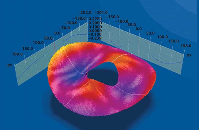
Figure 6. The shape of a disk platter is measured with a drive frequency of 3.069 kHz. This is a single frame from a movie made with a PhaseCam showing the platter vibrating.
With higher power lasers and more rapid A-O shutters, modes can be measured in the 10 to 50 kHz range. This is useful for measuring vibrating parts and scanning optics. Figure 6 shows some single frames from movies made of vibrating drive platters driven by a piezo speaker. The rapid exposure times also allow the measurement of rapidly moving parts. Figure 7 shows the measurement of a disk drive platter while the platter is spinning at 7200 rpm. This kind of data can help manufacturers better understand the dynamic performance of parts and components.
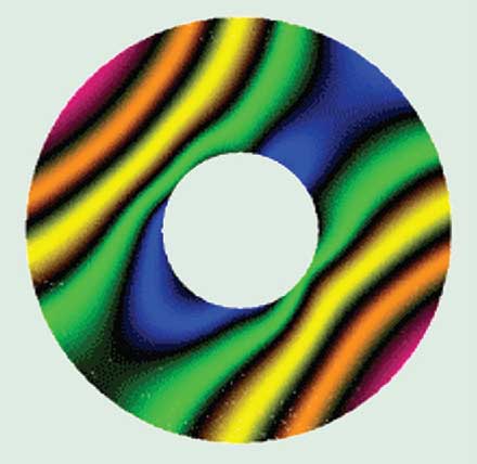
Figure 7. A 90-mm disk drive platter is measured while spinning at 7200 rpm with a 4D Technology FizCam. The surface shape is displayed using false color fringes to better show variations from the ideal flat surface.
The advent of very high speed, high resolution, dynamic interferometer systems like our PhaseCam and FizCam are changing interferometric measurement by enabling new measurement capabilities. These systems no longer require any type of vibration isolation to produce high-quality results over long path lengths in harsh environments. It is now possible to measure the shape of precision parts that are moving or vibrating to help understand the dynamic performance of a wide range of components. These capabilities are growing the market for a wide range of new interferometric measurements.