Full company details
Precision Glass & Optics (PG&O)
 3600 W Moore Ave.
Santa Ana, CA 92704-6835
United States
Designing Optics for Manufacturability: Bridging the Gap Between Engineering and Production
Photonics Spectra
Oct 2025A series of guidelines, tips, and best practices received directly from the manufacturer can help technically skilled engineers design better optics while lowering costs.DANIEL BUKATY JR., PRECISION GLASS & OPTICS (PG&O)
In the fabrication of optical components, one of the most common — and most critical — challenges to overcome originates well before the start of manufacturing. Despite abundant technical knowledge, many optical engineers responsible for the design of optical components ranging from basic plano windows to precision mirrors and advanced laser optics have never set foot in a manufacturing shop. This disconnect often results in overspecified or impractical designs that increase costs, lead time, and complexity without offering any improvement to performance.
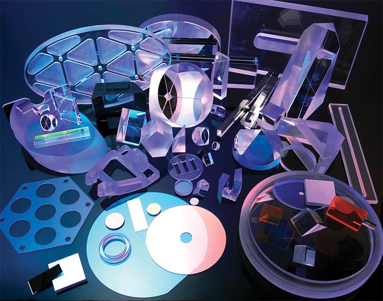
Courtesy of Precision Glass & Optics.
Though exceptions always exist, especially as optical design sophistication continues to rise, a set of practical insights from the manufacturing floor can offer real-world benefits to the engineers tasked with conceptualizing the designs of precision optics. These tips, suggestions, best practices, and guidelines aim to streamline the development of optics that are functional, cost-effective, and efficient to produce.
Flatness and transmitted wavefront error
One of the most frequent design challenges occurs when engineers rely on flatness as the sole metric for specifying optical windows — particularly those used in transmission. While flatness is a useful surface figure metric, it fails to accurately represent the performance that an optic will deliver when light passes through it.
Flatness is defined as the deviation of a surface from a perfect plane. This metric is typically specified in fractions of a wavelength, for example, λ/4 or λ/10 at 633 nm. It is measured via interferometry against a reference flat and applies to a wavefront reflected from a single surface. Engineers commonly rely on a measure of flatness when assessing how “good” a surface is.
Transmitted wavefront error (TWE), on the other hand, considers the entire optical path through the component. This metric accounts for the surface figure of both the front and back surfaces, internal refractive index variations (also known as inhomogeneity), and thickness nonuniformity. Another benefit of specifying TWE, therefore, is that it enables verification of homogeneity.
Simply, TWE is a more comprehensive
performance metric than flatness; it evaluates how well the part preserves the shape of a passing wavefront through the optic. Further, specifying only surface flatness can limit the ability to use double-sided polishing (DSP). DSP is ideal for windows, since it naturally balances material removal and creates symmetrical surfaces that complement each other, often yielding excellent TWE. However, if the specification is flatness only, it is necessary to polish each side of the optic separately and verify flatness independently. In addition to added labor, this increases the risk of mismatch and the overall cost.
Figure 1 shows an optic that has complementing convex and concave surfaces, which is a typical feature of DSP. Figure 2 shows an optic with excellent flatness but poor TWE. Figure 3 shows an optic with both excellent flatness and inhomogeneity in the material.
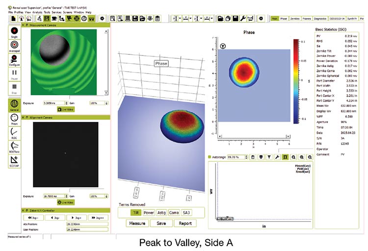
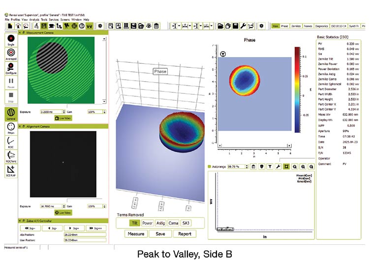
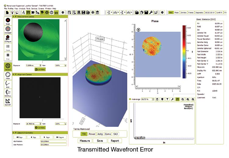
Figure 1. An optic with complementing convex and concave surfaces and excellent transmitted wavefront error (TWE), which is typical of double-sided polishing (DSP). Courtesy of Precision Glass & Optics.
Generally, if performance in transmission matters to an end user, specifying TWE is the only way to guarantee favorable results. The TWE specification will yield a better-performing optic, often at a lower cost.
Bevels: A mechanical necessity
Another common misconception is that bevels must be treated as precision
features, but they actually serve a
mechanical purpose: Bevels reduce the risk of edge chipping during handling and mounting. They are not optical surfaces and do not contribute to imaging or beam shaping. As a result, they rarely need to be held to tight tolerances.


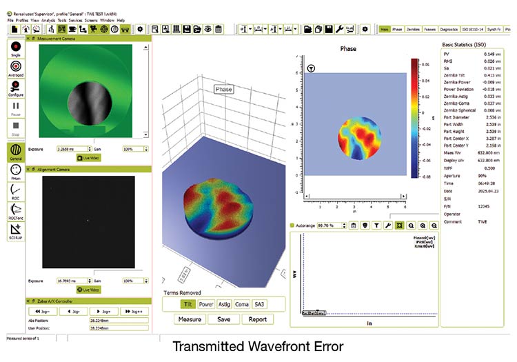
Figure 2. An optic that has excellent flatness but a weaker TWE. Courtesy of Precision Glass & Optics.
Frequently, though, drawings specify a part such as, for example, a 50-mm Ø × 3-mm-thick BK-7 part with a bevel of 0.25 mm ±.10 mm at 45° ±0.5°. These are very tight tolerances for bevels that will not interact with light. Such specs require slow, specialized processing, typically robotic or computer numerical control (CNC) edge beveling, and lengthy inspection. These labor-intensive steps can double the cost of an otherwise simple optic.
Worse still, in many cases, the optic has a 90% clear aperture, meaning a 2.5-mm-wide ring at the optic’s edge does not interact with light. In such a case, the bevel is specified more tightly than the surface that does affect performance. If the clear aperture of an optic is 90%, there is no benefit to specifying tight bevels in the remaining 10%. Instead, consider calling out the bevel as a “max” spec — for example, “0.5-mm max at any angle.” This allows the fabricator to process the edge quickly using hand tools or simple jigs. The part is equally as functional and far easier and less expensive to make.
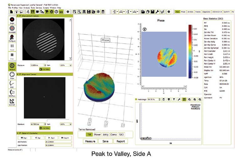

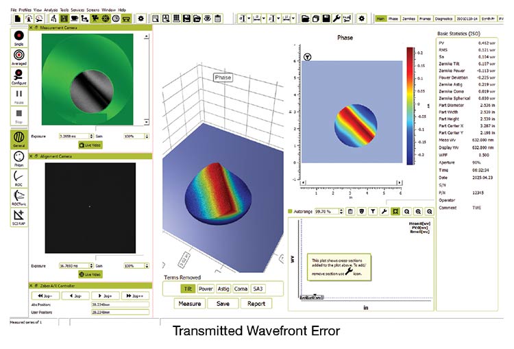
Figure 3. An optic that has excellent flatness and inhomogeneity in the material. Courtesy of Precision Glass & Optics.
It is also important to consider that tolerances are often set tighter than they need to be. While designers may err on the side of caution, overly tight specs can limit manufacturing options, drive up inspection time, and delay deliveries.
The fused silica trap
Fused silica is a fantastic optical material. Its homogeneity, thermal stability, and UV transmission are unmatched for many applications.
These advantages, however, do not make fused silica the optimal material for all applications. Especially for manufacturing mirrors, other materials offer significant benefits across multiple parameters.
In a typical mirror setup, such as a front-surface mirror coated with enhanced aluminum or silver, the light never travels through the substrate. Instead, it reflects off the front surface. So, many of the reasons designers choose fused silica — such as UV transmission or low birefringence — simply do not apply in the case of this material.
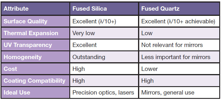
The use of fused quartz is an economical alternative. Fused quartz can be polished to the same surface figure and finish (λ/10 or better) when processed with proper pitch, slurry, and temperature control. It also offers effective thermal stability and supports a range of widely used coatings. Unless an application requires a high-power laser mirror or a multi-use optical system that undergoes thermal cycling, fused quartz will often provide identical performance at a significantly lower cost (see table).
Corner radius versus bevel
Often, customers may have a mechanical housing with a CNC-machined pocket
for an optical element. The pocket has radiused corners due to the toolpath of
an end mill. To match the pocket, the
designer will add radius corners to the optic.
The problem in this case involves the difficulty in rounding optics, since optics
naturally resist rounding. Machining radius corners into glass is expensive, requiring CNC grinding, multiple setups, and slow feed rates. All are apt to drive up costs.
A better approach is to use a 45° bevel at each corner of the optic. These can be produced with a belt sander after the optic is scribed to shape. This technique is fast, repeatable, and inexpensive, and it ensures that the part still fits the pocket.
Unless the optic must precisely match a radius — for example, an O-ring seal — beveled corners are almost always the smarter choice (Figure 4).
A Comparison of Fused Silica Versus Fused Quartz for Mirrors
Courtesy of Precision Glass & Optics.

Figure 4. A radius versus a bevel model. The green line indicates radius corners (top) and 45° beveled corners (bottom). Courtesy of Precision Glass & Optics.
The volume equation
In high-volume optics production, the economics of manufacturing change drastically. If tens of thousands or even hundreds of thousands of optics are needed from production, seemingly small decisions can carry massive financial implications. One such decision is whether to include a bevel at all.
When manufacturing at scale, Precision Glass & Optics often uses core drilling to produce circular optics. This is a fast, accurate approach that minimizes waste. However, beveling parts after core drilling can become a major bottleneck. If each bevel costs $1 in labor and 100,000 parts are needed from production, the cost is $100,000 — in beveling alone.
In many cases, the parts function perfectly well with just the core drilled edge, especially if they are assembled into fixtures, glued, or otherwise protected. For this reason, those involved in ensuring volume production should evaluate whether bevels are needed. If they are not optically or mechanically critical, omitting them can save thousands of dollars without sacrificing quality.
Involve your manufacturer early
The recurring theme in all these examples is that collaboration leads to better outcomes. Involving optical manufacturers early in the design process serves to ensure optimized specs and material selection that meet performance goals at reduced costs and with shorter lead times.
Meet the author
Daniel Bukaty Jr. is president of Precision Glass & Optics (PG&O), a global provider of commercial and precision end-to-end optical solutions. With more than 40 years of manufacturing expertise and a reputation for excellence, PG&O supports customers in defense, aerospace, biomedical, and industrial markets; email:
danjr@pgo.com.