
Polymer Optics Reveal That Discounting Aspheres Comes at a Cost
Though sometimes considered a nonstandard shape, aspheric optics offer advantages for a range of functions in optical system design and manufacturing.
By Dale Buralli
For centuries, the sphere has been the most widely used optical surface. This is due largely to the fact that traditional grinding and polishing techniques leverage the property that spheres fit together regardless of orientation.
The properties of a sphere enable simpler and more cost-effective mass production. But other characteristics also contribute to the sphere’s popularity
in optical design and manufacturing. In particular, a sphere is determined by a single parameter: its radius of curvature.
Spheres are also by far the easiest
surfaces to test, typically using interferometric methods.
Courtesy of iStock.com/iantfoto.
These advantages, however, should not be taken to imply that a spherical surface is necessarily the optimal choice for the shape of any particular optical surface. A classic — and telling — example is the simple exercise of determining the required shape that forms a perfect point image of a collimated beam (for example, an axial source point that is infinitely far away from the refracting or reflecting surface). Application of Fermat’s principle — the stationarity of allowed optical paths, known as rays — shows that the desired surface is either an ellipse, a hyperbola, or a parabola, depending on whether the change in refractive index at the surface is low to high, high to low, or reflective (Figure 1). Importantly, the type of conic section required depends on the details of the refraction or reflection behavior. Notably, the required optical surface is not spherical in any of the
Figure 1 geometries.
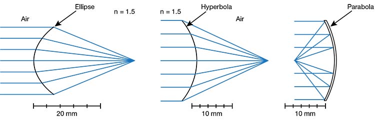
Figure 1. In each figure, the surface shape is chosen to form a perfect image of a collimated beam (object point at infinity). The required asphere, or type of conic section in this case, depends on the change in refractive index between the image space and object space. Courtesy of Apollo Optical.
This example considers the case of requiring a single surface to produce a geometrically perfect image. Most optical systems contain multiple surfaces, meaning the requirement that each surface produce a perfect image is overly restrictive.
In fact, a more common requirement is that the final image — after the light has propagated through the entire system — be of sufficient quality. The goal of optical design is to balance the aberrations of all the surfaces together in such a way that the pluses and minuses add up to an acceptably small value, typically not zero.
Beyond the sphere
Aberrations are a function of both surface shape and of how the surfaces are being used: the refractive indices on both sides of the surface, and the angles of incidence and refraction. For an on-axis object point, such as that considered earlier, the relevant aberration is spherical aberration, where rays passing through different points in the surface aperture focus at different axial locations.
Figure 2 shows an adaptation of a figure from Rudolf Kingslake’s textbook Lens Design Fundamentals. The image shows the longitudinal spherical aberration of a spherical refracting surface as
a function of the distance of the object
point from the surface. There are three
locations at which the spherical aberration vanishes: object at the surface, object at the center of curvature of the surface, and object at the aplanatic point. For most object positions, this positive-powered surface contributes undercorrected, or negative, longitudinal spherical aberration. For object positions between the surface and the aplanatic point, the surface contributes overcorrected, or positive, longitudinal spherical aberration. Designers must balance this combination of under- and overcorrection in overall system design.
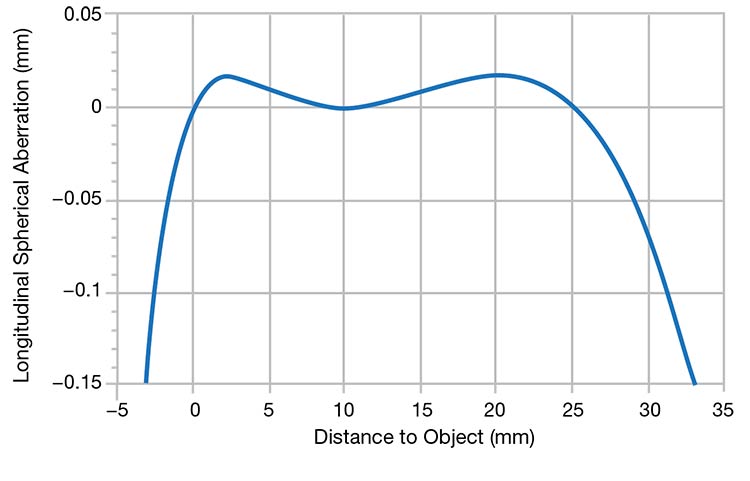
Figure 2. The longitudinal spherical aberration of a spherical refractive surface as a function of the distance from the surface to the object is shown. The surface has a radius of curvature of 10 mm, with air on the incident side and n = 1.5 on the refracted side; ray angle in object space = 11.5°. The three object positions for which the spherical aberration vanishes are at the surface (0 mm), at the center of curvature (10 mm), and at the aplanatic point (25 mm).
Courtesy of Apollo Optical.
As mentioned, the radius is the determining parameter of a sphere’s shape. Allowing the surface to be aspheric introduces additional parameters for the designer’s use. For example, in the single-surface perfect imaging case, the emergent parameter is the type of conic section used for the surface. In optical
design software, this is typically called the conic constant, which is zero for a sphere, −1 for a parabola, and so on.
Generally, though, “aspheric” just means “not a sphere”; any deviation from a sphere — and oftentimes some form
of polynomial — is possible. These additional parameters allow more “knobs” for the designer to adjust during system optimization and influence the aberration contributions from each surface.
Fabricating aspheric optics
That spherical surfaces do not necessarily produce perfect images is well known. The example in Figure 1 illustrates the utility of moving past a spherical shape when designing optical systems. At first glance, it is reasonable to assume that fabrication of an aspheric surface will be more difficult than the fabrication of a sphere. However, this conclusion is highly dependent on the particular manufacturing technique used.
Consider polymer optical elements. Most are produced via single-point diamond turning, either by directly turning the polymer itself, which is beneficial for prototype production, or by diamond turning an optical insert that is used for mass production processes such as injection molding. For a rotationally symmetric surface, whether spherical or aspheric, the path of the diamond tool must be programmed in 2D x-z space. In other words, a table of desired x and z values is generated and input to the single-point diamond turning machine controller (commonly called a “point cloud”). As this operation is the same whether a sphere or an asphere is desired, the cost of producing an asphere via single-point diamond turning is essentially nil in terms of both labor and financial investment.
This is not to say that designers should consider this approach for any conceivable surface; the specific equipment used to fabricate aspheric surfaces may impose surface sag or slope limitations, for example. Rather, designers and engineers should be mindful that discounting the use of aspheric surfaces may be unnecessary or impractical at the outset of the design.
Figure 3 shows the similarity of producing a rotationally symmetric asphere versus a sphere using AMETEK Precitech Inc.’s DIFFSYS software. As the input screen shows, the sphere is no more complex than a special case of a general rotationally symmetric surface; for a sphere, all aspheric terms are zero. After entering the values of the nonzero terms, the design effort relies strictly on mathematics, and the software generates the x-z points.
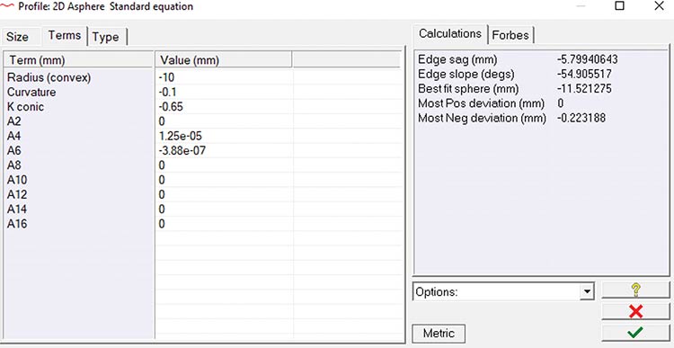
Figure 3. An example of a surface definition data entry window from DIFFSYS, software from AMETEK Precitech Inc. Spheres and rotationally symmetric aspheres are defined in the same window. Courtesy of Apollo Optical.
Finding advantages
Manufacturing aspheric surfaces without added cost or time in the fabrication stage does not, unfortunately, eliminate all the advantages of using a sphere. In particular, the relative ease of testing remains a tangible benefit of spheres compared with aspheres, regardless of how the aspheric surface is made. In fact, it may be advantageous to leave some surfaces in a complex system as spherical to ease the metrology burden and potentially reduce the overall cost of the system.
Another advantage of a sphere is that it is easy to communicate its shape with only two pieces of information: the radius of curvature and whether the surface is convex or concave when viewed from air. The “not a sphere” surface, on the other hand, opens the door to a myriad of possible definitions. Different optical design software programs use different definitions of, for example, polynomial-defined asphericity. Also, the sign convention used to define the coefficients of a polynomial may differ for the optical designer, optical manufacturer, and metrologist. While it may be as easy to manufacture a sphere as an asphere, care should be taken to ensure that the surface is not made “exactly wrong.”
Yet while these parameters may be beyond the control of the engineering and development team, other factors are more easily addressed. By working closely
together, the designer and manufacturer can ensure that the desired aspheric surface is defined and communicated accurately, thereby avoiding potentially costly bottlenecks.
Additionally, producing an asphere as easily as a sphere aids in reducing surface errors in molded optics. All thermoplastic materials shrink as they cool in an injection mold. Pre-adjusting the shape of the diamond-turned inserts that form the
optical surfaces of the molded lens
compensates for the majority of this shrinkage. However, depending on the shape of the lens or the tightness of the form tolerances, it may be impossible to precorrect the inserts for all resulting form error. In this case, it is desirable to recut the inserts to null out the residual form error. The shapes required for this compensation will almost always be aspheric. In fact, it may be impossible to represent the shape efficiently with a polynomial. Since the single-point diamond-turning machine expects a table of x and z values, using the surface error directly as a point cloud bypasses any additional issue.
In summary, designers and end users should avoid discounting the use of aspheric optics solely because of the risk of increased production costs. Polymer optical elements can implement aspheric surfaces without additional manufacturing time or complexity.
Meet the author
Dale Buralli is chief scientist at Apollo Optical Systems in West Henrietta, N.Y. He received his Ph.D. from the Institute of Optics at the University of Rochester, where he is an adjunct professor; email: buralli@apollooptical.com.
/Buyers-Guide/Apollo-Optical-Systems-Inc/c940