The performance of high-speed, digital fiber optic communications systems depends upon how reliably the receiver is able to distinguish closely spaced bits of information. Dispersive effects — physical mechanisms that broaden transmitted pulses — degrade this process.
Paul Hernday, Fiber Optic Measurement Training and Consulting
There are three fundamentally different dispersive phenomena in optical fiber, of which polarization mode dispersion (PMD) is the most complex. In digital multimode fiber systems, a light pulse separates into multiple spatial paths or modes. Each component reaches the receiver at a slightly different time (Figure 1), broadening the received pulse. Single-mode fiber solves the differential mode delay problem, allowing data rates to be increased until chromatic dispersion — the variation of propagation speed with wavelength — produces unacceptable pulse spreading. The amount of chromatic dispersion that a system can tolerate is inversely proportional to the square of the bit rate because an increased data rate means not only a wider spectrum and increased spreading, but also narrower bit slots that are more sensitive to the spreading of neighboring pulses.
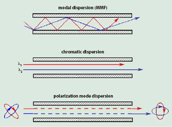
Figure 1. In the three types of dispersion in optical fiber, components of the signal are delayed differentially, broadening the pulse.
When chromatic dispersion is compensated — typically to a small but nonzero value in dense wavelength division multiplexed (DWDM) systems — the bit rate can be increased until it is limited by the third dispersive effect, PMD. Every network exhibits two slightly different propagation delays that correspond to different input polarizations. Some of the pulse energy experiences the longer delay and the rest of the energy experiences the shorter delay. As with the other dispersive effects, the result is a broadening of the received pulse.
PMD is considerably more subtle and interesting than this, however, and the topic accounts for a rapidly growing body of technical literature. This article will explore the origins, statistical character, measurement and mitigation of first-order polarization mode dispersion.
Properties of polarized light
The electric and magnetic fields of a lightwave fluctuate at right angles to one another in the plane perpendicular to the direction of propagation. Polarization is defined in terms of the electric field, which interacts more strongly with most devices. The electric field of a fully polarized, monochromatic lightwave can be described as issuing from a point charge moving in an elliptical pattern in the plane of the source (Figure 2). Details of the ellipse — the ratio of major to minor axis, the angular orientation and handedness (direction of rotation) — describe the state of polarization of the light. Linear and circular polarizations are simply extreme cases of elliptical polarization.
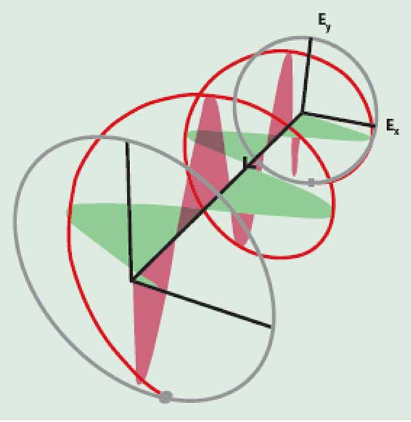
Figure 2. The electric field of right-hand circularly polarized light (helix), and the field components along the X- and Y-axes.
A graphical shorthand representation of polarization states is provided via the Poincaré sphere1 (Figure 3). Each point on the surface of the sphere represents a unique state of polarization. Linear states fall on the equator and circular states at the poles. Right-handed and left-handed elliptical states fall in the northern and southern hemispheres, respectively.
Polarization states diametrically opposite one another are mathematically independent, a condition called orthogonality. Linear horizontal and vertical polarizations are examples of orthogonal states; light emerging from a horizontal polarizer is blocked by a vertical polarizer. Any two orthogonally polarized, same-frequency lights can serve as the raw materials, or basis states, from which, by adjustment of relative delays and intensities, any other state can be synthesized. In Figure 2, the horizontal and vertical polarization states act as basis states to form circularly polarized light. In this case, the basis state waves are of equal intensity but are offset 90° in phase (one quarter wave of relative delay).
The origins of PMD
The speed of propagation of a lightwave depends on the index of refraction of the transmission medium in the direction of fluctuation of the electric field. Consider a short, straight length of single-mode fiber. Given an index difference between the X- and Y-directions, a Z-traveling wave decomposes into a pair of waves having X- and Y-directed electric fields. The two waves propagate at slightly different speeds, accumulating an optical phase shift and associated differential delay in proportion to distance. A transmission medium that produces a phase shift in this way is said to be birefringent. The natural birefringence of quartz and calcite account for their use in optical retarders and wave plates.
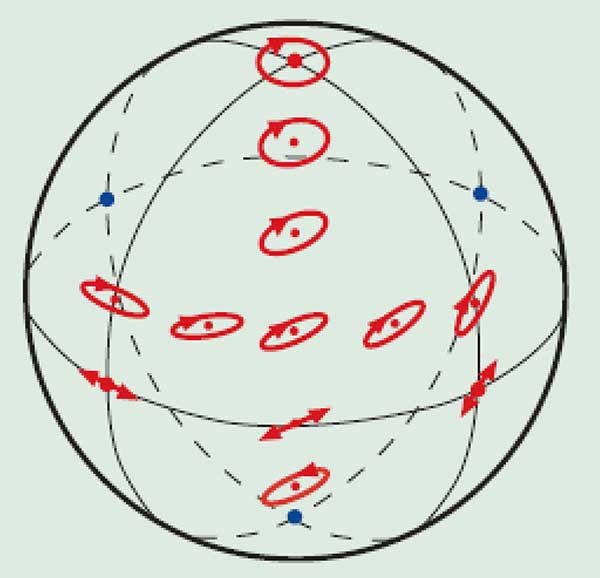
Figure 3. Each point on the Poincaré sphere represents a unique polarization state.
PMD in single-mode optical fiber originates with noncircularity of the core (Figure 4a). Fiber birefringence has two components. Form birefringence is a basic characteristic of any oval waveguide. Stress birefringence — generally dominant — is induced by the mechanical stress field that is set up when the fiber is drawn to other than a perfectly circular shape. Over short lengths, fiber birefringence splits the input pulse into linear slow and fast polarization modes, behaving like a linearly birefringent crystal. The corresponding difference in propagation time is called the differential group delay (DGD), expressed in picoseconds (1 ps = 10-12 s). Together, the differential group delay and the orthogonal polarization modes are the fundamental manifestations of first-order PMD.
In practice, only relatively short, straight, undisturbed lengths of transmission fiber behave as simple, uniform birefringences. Spooled, cabled or deployed fiber is more accurately modeled as a chain of simple birefringent fiber segments spliced at random rotational angles (Figure 4b). By changing the relative phase of the local fast and slow waves, each segment transforms its input polarization state into some other output state. This output state illuminates the following segment, where the wave again breaks down into the local fast and slow modes and the process repeats. Given the extremely weak birefringence of telecom fiber, mode coupling is easily induced in the fiber by the mechanical forces arising from spooling, cabling or installation.
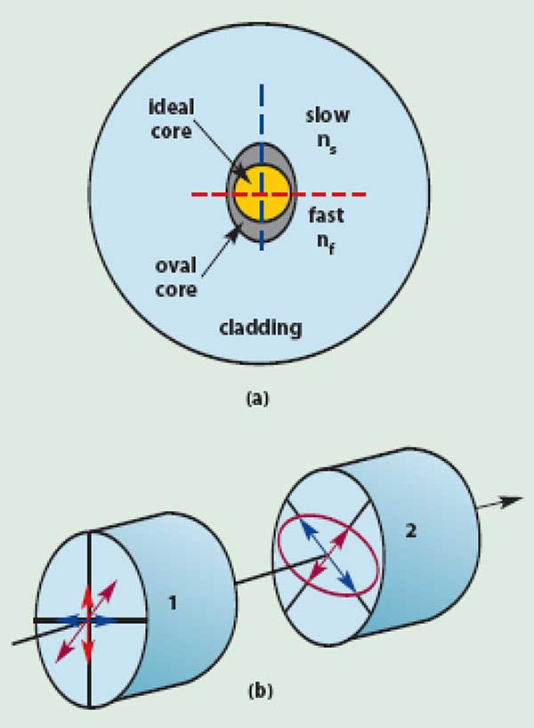
Figure 4. Core noncircularity (exaggerated) is the root of PMD in single-mode fiber.
The action at the interface of adjacent birefringent elements is called polarization mode coupling, and it is this phenomenon that causes the differential group delay of single-mode fiber to vary with both wavelength and environment (time). Fiber spans that contain a large number of mode-coupling events are called randomly mode-coupled. In such a fiber, the distribution of differential group delay values over wavelength tends toward a Maxwell curve. The differential group delay is also Maxwell distributed across temperature at a fixed wavelength, given sufficient temperature change.
The polarization mode dispersion of a randomly mode-coupled span is described in several ways. The differential group delay at a given wavelength and time is called the instantaneous differential group delay. The average value of the DGD over wavelength is called the PMD delay. The average DGD divided by the square root of fiber length is called the PMD coefficient. Confusion can occur when the general label “PMD” is used alone in place of one of these more specific descriptors.
The presence of mode coupling affects more than the character of the differential group delay; the fast and slow polarization modes become elliptical states and, in addition, they vary with wavelength and time. However, at any given wavelength and time, and in the absence of polarization-dependent loss, there exist, at the input of the fiber, an orthogonal pair of states that correspond to early and late arrival of energy at the output of the fiber path.2 These special input states are called the principal states of polarization (PSPs). They are often referred to as the fast and slow polarization modes. There is another pair of principal states at the output of the fiber path. Energy coupled entirely to the fast polarization mode or principal state at the input emerges in the fast polarization mode at the output. In general, the input and corresponding output PSPs are different. Since the PSPs are the manifestation of the random configuration of birefringences and mode couplings that make up the fiber path, any change in these details causes a corresponding shift in the PSPs.
The defining feature of an input/output principal state pair, for example the input and output fast polarization modes, is that the transformation between these two states is independent of wavelength over a suitably narrow wavelength interval. The average value (over wavelength) of the narrow frequency interval over which PSPs are frequency independent is called the PSP bandwidth.
When the spectral width of the signal exceeds the PSP bandwidth, both the differential group delay and the PSPs vary across the signal spectrum. This produces higher order PMD effects, including both a chromatic dispersion component and a pulse distortion arising from a shift in the principal states of polarization across the pulse spectrum.
The impact of first-order PMD on an operating link depends upon both the differential group delay and the relative intensities of light in the principal states of polarization. The impairment is most severe when equal amounts of light are coupled into the input principal states of polarization, and the impairment is negligible when all of the light is coupled to a single principal state of polarization.
How much can be tolerated?
Digital transmission systems are designed to tolerate 10 to 15 percent of a bit period of average differential group delay, or 10 to 15 ps for a 10 Gb/s system. The average differential group delay of long routes of legacy fiber is often greater than this limit and in particularly severe cases can exceed 100 ps. Measurement of the PMD of installed fiber is a key step in upgrading to higher data rates. First-order PMD can be mitigated, but the amount of improvement is limited by the unmitigated effects of second-order PMD.
New optical fiber generally exhibits an average differential group delay in the range of 0.05 to 0.10 ps/km1/2. Spun fiber is so called because the fiber is rotated back and forth as it is drawn from the heated preform. This radically increases the amount of mode coupling, preventing the accumulation of uniform birefringence and yielding a particularly low PMD fiber. Optical components also exhibit PMD, and service in 10+ Gb/s systems imposes maximum DGD specifications in the range of 0.05 to 0.25 ps. Most optical components by themselves do not exhibit mode coupling.
Measurement of PMD
PMD measurement methods can be divided into two broad categories. Methods of the first category determine PMD from the measured variation of output polarization with wavelength. This category can be further divided into narrowband and broadband methods. Narrowband methods determine PMD from the variation of output polarization over narrow wavelength intervals, typically narrower than the principal state bandwidth of the fiber under test. Methods of this type include Jones matrix eigenanalysis (JME),3 Poincaré sphere analysis (PSA),4 and Mueller matrix method (MMM).5 Broadband methods determine PMD from the variation of output polarization over a broad wavelength range. Methods of this type include the fixed analyzer (or wavelength scanning) method and its variations.
The second broad category of PMD methods includes those that determine PMD from the measured difference in the propagation time associated with the two input polarization modes (PSPs). This category can be further divided into low-coherence interferometric6 and modulation phase shift1,7,8,9 methods.
A representative of the narrowband polarimetric techniques is the JME method (Figure 5). The Jones matrix is a mathematical description of the polarization transforming properties of a two-port device or fiber. Measurement of the Jones matrix involves stimulating the test path with a set of three known polarization states and measuring the corresponding output states. The process is repeated at a series of closely spaced wavelengths. The optical source is usually a tunable laser. Adjacent pairs of Jones matrices are analyzed to obtain a graph of the differential group delay versus wavelength. The PMD coefficient is obtained by dividing the average of these DGD (values) by the square root of the fiber length.
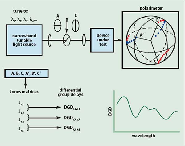
Figure 5. The Jones matrix eigenanalysis polarization dispersion method provides a detailed description of the differential group delay as a function of wavelength.
Narrowband polarimetric methods are used in R&D, manufacturing, incoming inspection and metrology, and more recently in the field for characterization of installed fiber. They are also applicable to the measurement of erbium-doped fiber amplifiers. The wavelength specificity of these methods allows them to gather detailed statistics of fiber PMD, measure the first- and second-order PMD of specific channels, and determine the DGD ripple of narrowband components.
Narrowband systems designed for field applications can tolerate fiber movement during the measurement.
A recent addition to the polarimetric methods is swept laser interferometry. In this measurement the test device and a reference fiber are embedded in parallel between two optical directional couplers. The swept laser output is split by the first coupler into reference and test paths and then recombined by the second coupler. Detection of these superimposed lightwaves through a polarizer produces a beat tone that is proportional to the difference in group delay between the test and reference paths. If the test device exhibits group delay variation over frequency, this will be reflected in fine variations in the beat tone. In practice, a polarization diverse receiver extracts enough information to perform the equivalent of a narrowband JME measurement. The swept laser interferometric method generally provides not only the PMD but also the chromatic dispersion, insertion loss, and polarization dependent loss. The method is applicable to optical components but is not useful for devices containing more than approximately 10 to 20 m of fiber.
The broadband polarimetric methods consist primarily of the fixed analyzer method and its variations (Figure 6). For fiber measurements, the wavelength is swept as widely as possible and the corresponding evolution of the output state of polarization is analyzed. Given sufficient wavelength range, the output states approach a random walk pattern when viewed on the Poincaré sphere. The details of this pattern reflect the random interplay of local fiber birefringences and mode couplings. In the most complete form of this method, a polarimeter captures the evolving polarization state in full detail and projects it onto the three axes of the Poincaré sphere. This produces three plots of the normalized Stokes parameters across wavelength. Plots of higher PMD fibers show a greater density of peaks and valleys. A calculation involving the measured density of peaks and valleys yields a single PMD delay value that represents the average differential group delay.
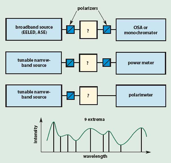
Figure 6. The fixed analyzer (wavelength scanning) method determines an average differential group delay value from the transmission through a polarizer.
The fixed analyzer method is more commonly implemented using a simple linear polarizer to discriminate changes in output polarization. Although this setup captures less of the polarization information and therefore is less reproducible at low PMD values, this setup is easy to implement using a tunable laser and power meter (or a broadband light source and spectrum analyzer) as the transmitter and receiver. Fixed analyzer plots can also be interpreted using Fourier analysis. The presence of deterministic spikes in the Fourier response suggests the presence of one or more uniform, high-birefringence segments somewhere along the fiber span.
The fixed analyzer method is used in situations where only the average differential group delay value is needed. Example applications are the surveying of installed fibers, and the screening of fibers and cables in manufacturing. The method is seldom used to test narrowband components because the combination of low differential group delay and small wavelength span results in too little polarization variation for an accurate measurement.
The second broad category of PMD methods includes those that determine PMD directly or indirectly from the measured difference in propagation time of the two polarization modes. This category can be further divided into the low-coherence interferometric and the modulation phase shift methods.
The low-coherence interferometric method is shown in Figure 7. The input of the test device is illuminated by a polarized broadband source and the output is coupled to an interferometer. Light from both output PSPs couples to both legs of the interferometer and then to a polarizer where the two polarization modes interfere. The interference envelope is detected and displayed against a differential delay time calculated from the mirror position. The interferogram of a simple optical component shows a central peak and two equally spaced outlying peaks. The outer peaks occur at mirror positions for which the absolute value of the time imbalance of the interferometer legs matches the differential group delay of the test device. The DGD value is simply the time difference between the central peak and either outlying peak.
The interferogram of a randomly mode-coupled fiber (Figure 7) resembles a Gaussian function multiplied by noise. A fiber with higher average DGD produces a wider interferogram. The average DGD of the fiber is calculated from the width of a Gaussian curve fitted to the interferogram, or from the statistical second moment of the data. Like the fixed analyzer method, the low-coherence interferometric method determines the average differential group delay value over the wavelength range of the optical source. Interferometry is used in fiber and cable plants, and in the field to survey the average differential group delay of installed fiber. It can measure the differential group delay of optical components to relatively low levels with the use of special techniques, and in some configurations can also measure relatively narrowband devices.
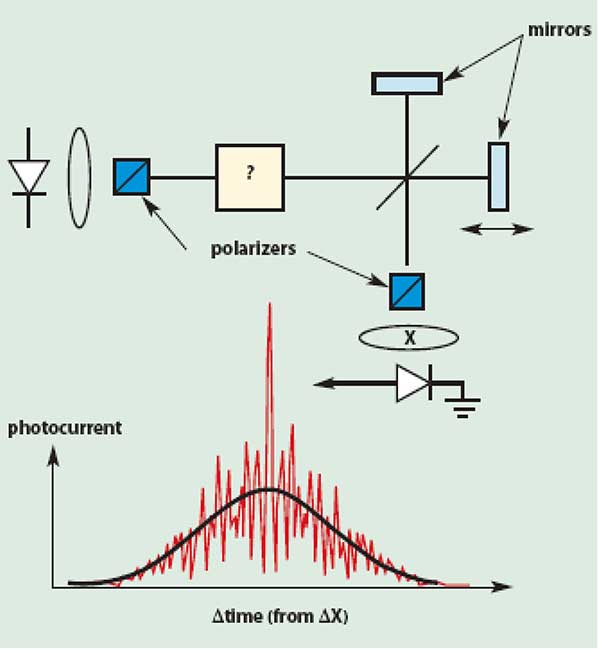
Figure 7. Low-coherence interferometry determines an average differential group delay value from the width of the electric field autocorrelation function.
The modulation phase shift1 methods determine the differential group delay from measurement of the modulation phase shift between light exiting the test device in the fast and slow polarization modes. The optical source is typically a tunable external cavity laser. High-frequency systems typically employ lithium niobate Mach-Zehnder modulators. The modulation phase is recovered after a photodetector by an RF phase comparator, using the RF source as a phase reference. In the most basic form of the method, the input polarization of the test device is scanned, and the detector system monitors the rise and fall of the RF phase. The measured extremes of phase correspond to transmission at the fast and slow polarization modes, and the differential group delay is easily calculated from the peak-to-peak phase shift and the frequency of the RF modulation. Enhancements of this method include techniques in which a pattern of four well-known polarization states are sequentially applied to the test path.7,8,9 From the corresponding four phase shift measurements, the differential group delay is calculated. This more comprehensive approach can also determine the higher-order PMD as a function of wavelength.
The family of PMD measurement methods is large and expanding. Standardized test procedures for the methods are available from the Telecommunications Industry Association (TIA) and from Global Engineering Documents.
PMD mitigation
The development of PMD mitigation techniques is driven by the upgrade of legacy fiber links to 10+ Gb/s. Any mitigation scheme must account for random changes in the differential group delay and principal states of polarization. One approach is to eliminate pulse spreading by coupling the transmitter output to a single input principal state of polarization of the link. Drawbacks are the need for specialized hardware at both transmitter and receiver and the delay of the feedback loop, which is twice the length of the link.
PMD mitigation can also be implemented optically before the receiver (Figure 8). Under feedback control from an impairment detector, a polarization controller adjusts the relationship between the link and the DGD compensator. A length of polarization maintaining fiber makes a low-cost DGD compensator, but polarizing delay lines — mechanical or integrated circuit — can provide an adjustable differential group delay. In principle, a cascade of multiple polarization controller/differential group delay compensator pairs could more fully compensate for PMD at the sacrifice of economy and speed. There are two basic strategies for receiver-based optical compensators. One strategy is to cancel the link differential group delay, and the other strategy is to rotate the polarization of the optical signal before the receiver to coincide with an output principal state of polarization of the overall system (link plus DGD compensator).
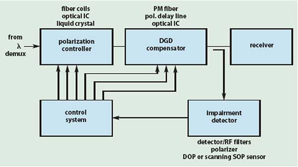
Figure 8. Receiver-based optical PMD mitigation shows competing technologies.
PMD can also be electrically mitigated by means of an equalizer circuit installed following the receiver photodetector. The detected signal is split into several paths to be differentially delayed and scaled, then recombined to squeeze the pulse back to a narrower shape. This technique has a history in microwave communications. PMD mitigation is receiving wide research attention and field trials have been run on several methods.
Summary
When chromatic dispersion is compensated, PMD becomes a bit-rate limiting factor in digital fiber optic communications systems. The high PMD of many legacy fibers calls for measurement of the installed fibers and motivates the development of PMD mitigation. Specifications for components and fibers are tightening, and an understanding of polarized light and its interaction with hardware has become a key success factor for component manufacturers.
References
1. Derickson, Dennis, ed. (1998). Fiber-optic test and measurement. Prentice Hall, New Jersey.
2. Poole, C. et al (1986). Elect. Lett. Vol. 22, p. 1029.
3. Heffner, B.L. (1992), IEEE Phot. Techn. Lett., Vol. 4, p. 1066.
4. Cyr, N. et al, Digest of CLEO/Pacific Rim 1999.
5. Nelson, L. et al, Digest of ECOC 1999.
6. Gisin, N. et al (1991), IEEE J. Lightwave Techn., Vol. LT-9, p. 821 and references therein.
7. Williams, P.A. (1999). Elect. Lett. Vol. 35, p. 1578.
8. Barlow, A.J. et al, Digest of OFMC 2000.
9. Jopson, R. et al, Digest of LEOS 1999 (postdeadline).