The versatility of polymer optics opens new doors for optical designers who understand the whys and hows of specifications.
William S. Beich, GS PLASTIC OPTICS
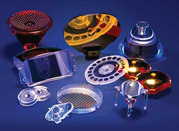
The use of precision polymer optics is becoming an increasing necessity today as products demand sophisticated light handling components to achieve desired results. Polymer optics can be thought of as an important enabling technology allowing the successful development of many types of devices. Key advantages that polymer optics have over competing glass solutions include lighter weight; the ability to integrate mechanical and optical features; and the ability to reproduce aspheric, freeform, and other complex geometric surfaces.
 The unique nature of thermoplastics and of the injection molding process itself demands a disciplined approach during all phases of manufacturing, from component design through prototyping and finally to production. The best outcomes are achieved when the design team (usually made up of optical and mechanical designers) understands the manufacturing process and works closely with a manufacturer who specializes in this field.
Types of applications
Essentially any application that calls for an optical component, whether for imaging, scanning, machine vision, medical, or general illumination, is a candidate for using a polymer optic. The list of potential applications is large and growing.
Polymer optics can be found in supermarket bar-code scanners (both laser scanners and 2D readers), lidar and other time-of-flight applications, and in many different types of medical applications ranging from point-of-care (POC) assay containers to lighted surgical retractors. They are also used in document scanners and in sophisticated laboratory equipment such as spectrometers and cleanroom particle counters. As applications continue to grow, polymer optics can be found in telecommunications products and are often used with microstructured surfaces such as microlens arrays and diffractive optical elements. Polymer optics are used routinely in ever-growing LED illumination applications.

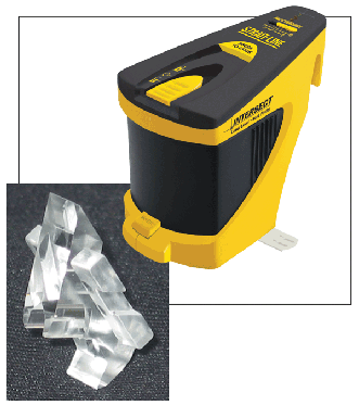
Element design and finished product. The Intersect Laser Level is designed and manufactured by Irwin Industrial Tools.
Other examples include imaging systems for near-to-the-eye displays. Polymer optics are frequently found in PC peripherals, such as videoconferencing cameras and microscopes, and in consumer devices such as compact disc and DVD players, and smartphones.
As noted above, this wide array of applications results from the key advantages that polymer optics have over competing glass solutions. Since these advantages are directly related to the materials and the injection-molding process it is critical to understand the materials and the manufacturing methods used.
Thermoplastics
The principal optical molding materials are acrylic, styrene, polycarbonate, cyclic-olefin polymers (COPs, such as Zeonex and Zeonor, manufactured by Zeon Chemicals), and cyclic-olefin copolymers (COCs, such as Topas, manufactured by Topas Advanced Polymers). There are other specialty resins such as Ultem (polyetherimide, or PEI, manufactured by Sabic), and polyesters, (such as OKP-4 and OKP-4 HT, made by Osaka Gas Chemical). All of these materials are thermoplastics, which means they can be heated and cooled repeatedly. This category of polymer is different from the optical-grade thermoset plastics, which, once cured, are not able to become molten again.

The manufacturers of these materials publish data related to their mechanical and optical properties. Optical designers need to understand how these materials behave in all environments so that they can arrive at appropriate solutions. Tables 1 and 2 summarize the important optical and mechanical data presented below.
Mechanical properties
Thermal expansion — The coefficient of thermal expansion for optical plastics is approximately an order of magnitude greater than that of glass. This is an important property to consider when designing an optical system that is intended to operate over a wide temperature band. If the system cannot be refocused, other techniques must be considered to achieve athermalization.
Maximum operating temperatures — When compared with glass, most optical thermoplastics have a fairly low glass transition temperature (Tg). This can range from the 80 to 90 °C for polystyrene and acrylic to about 130 °C for polycarbonates, Topas, COPs, and some polyesters. Some specialty polymers have higher Tgs. For example, Grilamid (a transparent polyamide) has a Tg of about 160 °C. Ultem has a Tg of about 217 °C.
Water absorption — Most thermoplastics (with the exception of COP and COC materials) will absorb water, which will cause any optic made of this material to change dimensionally. For example, acrylic will absorb approximately 0.3% water over a 24-h period. During the same period, a COP or COC material may absorb only 0.01%.
Weight — For a given volume, polymers are lighter weight than glass. Because of this property, an optic molded from a thermoplastic will weigh less than a corresponding glass optic. Moreover, thermoplastics can offer higher impact resistance (this is especially true of a more ductile material such as polycarbonate).
Optical properties
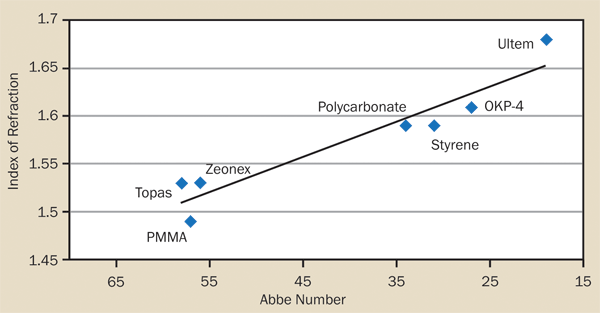
Index of refraction, Abbe number — The range of available indices of refraction is narrow when compared to that available for glass. Acrylics and COP materials behave more like crown glass types (having Abbe values in the mid-50s), with an index of refraction of about 1.49 and 1.53, respectively. On the other hand, styrene and polycarbonate behave more like flints (with Abbe values in the low to mid-30s) and having an index of refraction of about 1.59, as shown in Figure 1.

Figure 1. Relationship between index of refraction and Abbe numbers for commonly used
optical thermoplastics.
Change in refractive index with temperature (dn/dt) — Polymers will exhibit a change in index of refraction relative to temperature. The thermoplastic dn/dt is fairly large (about 20 times that of glass) and negative (i.e., as the temperature goes up, the refractive index goes down).
Transmission — Most optical polymers have high clarity in the broadband visible portion of the spectrum (~400 to 650 nm). For example, acrylic and some grades of Zeonex have transmission properties of about 92%. Materials such as polycarbonate and polystyrene have slightly lower transmission. Ultem, which has good transmission in the near-IR, may not be suitable for broadband visible applications because it absorbs in the blue end of the visible spectrum.
Birefringence — The amount of birefringence a system can tolerate is an important design consideration and should be discussed with the manufacturer early in the process. Some polymers such as polycarbonate and polystyrene have a higher amount of stress to begin with because of their polymer properties. The amount of birefringence in an optic can be exacerbated by poor part design and/or poor gate location in the mold. Table 2 summarizes the amount of stress inherent in the different optical polymers. Because birefringence can be difficult to measure, a qualitative rating system of 0 to 10 was used. In this scale, 0 is the lowest amount of stress, and 10 is the highest amount of stress.

The manufacturing process
Injection molding is a cost-effective way to replicate spherical, aspheric, and free-form surfaces and combine them with mounting features. There are three main components to successful injection molding: (1) the mold, (2) the injection molding machine, and (3) the process used to perform the operation.
The mold — The mold used to manufacture polymer optics has three main features: (1) the cavity details, (2) the optical inserts, and (3) the housing that holds the cavities and inserts. One key advantage of using polymer optics is the ability to combine optical and mechanical features into one platform. Depending upon the nature of the mechanical features being considered, the mold itself will take on additional complexity.
The mold is built to the negative of the final part. For example, if the final optic has a convex surface, the optical insert will be concave. The mechanical features of the part have to be drafted to allow for easy removal after the molding process is complete. Today most optical inserts are made of nonferrous alloys that have been diamond turned to the final prescription. This allows for a very high degree of accuracy in the final optics.
During the molding process, all thermoplastics shrink as they cool. In general the shrinkage is approximately 0.5 to 0.6%. It is important that the shrinkage be taken into consideration when determining the final dimensions of the mold.
Using state-of-the-art CNC lathes to make the optical inserts makes it possible to deterministically create on- and off-axis aspheric surfaces as well as freeform optics. This technology also allows the optical molder the flexibility of adjusting the inserts for shrinkage after initial molding trials have been completed.
The molding machine — The optical injection-molding machine, also called a press, consists of a fixed and a moving platen, a clamping unit, and an injection unit. The mold is placed in the press with one half mounted to the fixed platen and the other half mounted to the moving platen. Plastic pellets fed into the injection unit are plasticized into a molten state and injected into a mold. The clamp mechanism holds the two mold halves together during this injection process. As the polymer cools and solidifies in the mold, the material takes on the shape of the insert and cavity details, creating the final optic. After cooling, the mold opens and ejects the finished optic attached to its runner system, from which it is later removed.
The process — As described above, the combination of equipment used in injection molding is complex with many variables and control parameters. Without the development of a robust process, even the best mold and operators will likely experience drift over time. This process drift may come from tool wear, changes in ambient conditions, minor fluctuations in resin content to name a few. Development of a robust injection-molding process is essential and seeking out a manufacturer that is highly skilled in scientific molding techniques is advised.
Optical injection-molding techniques can reproduce optics with a high degree of repeatability and accuracy. Much of this is due to the precision of the molding press as well as to the precision built into the mold itself. A mold’s construction typically exhibits a tighter set of tolerances than those required of the components it produces. An experienced optical molder, therefore, should dictate how the mold is to be constructed.
If there is uncertainty about how a part will process in the press, the mold can be built “steel-safe.” That is, it will be built to smaller dimensions than the nominal final dimensions of the part, allowing the mold maker to make very fine adjustments once initial molding trials have been performed. Part geometry, part size, the choice of material, the overall mold design, the gate scheme, and a host of process issues all play critical roles in the quality of the final product.
In some instances, it is possible to create economies of scale by building molds that have more than one cavity in them. With multicavity molds, more than one optic is produced during each molding cycle.
Coatings — Polymer optics can be coated using physical vapor deposition. Coatings on polymer substrates are applied at lower temperatures and have less durability than coatings applied to glass substrates. It is possible to specify reflective, antireflection, beamsplitter, and conductive coatings for a wide variety of polymer substrates. Antireflection coatings can be multilayer (with an average surface reflectivity of less than 1% over a range of 450 to 650 nm) or single-layer MgF2 (with an average surface reflectivity of about 1.5% from 450 to 650 nm).
Reflective coatings of silver, as well as protected and enhanced aluminum and gold, are routinely applied and can be used to create first- or second-surface mirrors. In some cases a protective overcoat can be applied to metal coatings to improve abrasion resistance.
In addition, it is possible to apply hard coatings to polymer optics. Hard coatings were originally developed to protect polycarbonate ophthalmic lens blanks. Additional formulations of this type of coating have been developed to allow hard coatings on different types of polymer substrates. It is also possible to apply hydrophobic and antifog coatings to polymer substrates.
Things to consider up front
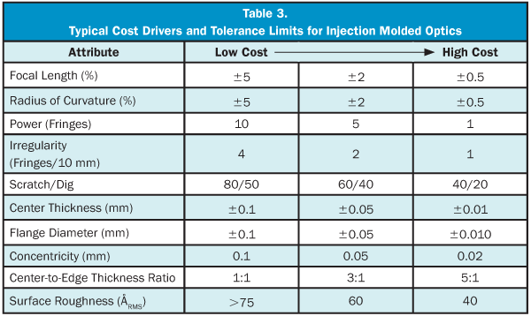
It is important for the optical molder to approach each project on a case-by-case basis, taking into account all of the variables. Table 3 summarizes some rules related to tolerances in terms of the impact stated tolerances may have on final part cost. The following serves as a starting point for discussion with the optical molder.

• Think about the environment in which the optic/system will be used. Does the system have to operate (or maintain focus) over extremes of temperature, or in high humidity?
• Is polarization an issue?
• When do you need the optic?
• Will you need prototypes?
• What is the quantity you will require in production? Should you be thinking about a multicavity mold?
• A basic specification is the optical form. The ideal shape for molding is a nearly uniform wall thickness.
• The overall part design should be as symmetrical as possible to optimize the melt flow in the mold. Strong meniscus, biconvex, and biconcave shapes should be avoided. It is sometimes better to make two optics of more uniform thickness than one optic with very strong surfaces.
• Extreme variations in part thickness can cause uneven flow characteristics. Large, thick, or uneven parts may require detailed three-dimensional mold flow and cooling analysis to model how the element will fill during the molding process. This exercise usually is undertaken early in the design cycle.
• A thinner optic presents fewer shrinkage-compensation issues and shorter cycle times, translating into less costly parts.
• Optics with thicker cross sections not only require increased cycle times to mold, but also present a greater challenge in terms of maintaining higher surface figure accuracy.
• Because flat surfaces have a tendency to sink as they cool in the mold, one should add a surface of power on both sides of the optic whenever possible.
Selecting the right optical molder
Optical designers are well advised to partner with an optical molder who thoroughly understands the engineering issues. The optical molder should be involved in the process as early on as possible.
It is in the designer’s best interest to visit the molder’s manufacturing facility to assess its capabilities. It is important to realize that the parts produced will be no better than the tools in which they are molded.
However, good tooling alone does not guarantee that good parts will be molded. A complete understanding of the optical molding process is the driving factor in producing precision polymer optics and Scientific Molding Technology (SMT) is highly recommended. SMT is a data-driven approach to developing, implementing, documenting, maintaining, and troubleshooting an injection molding process.
It is critical that the molder have the metrology capability in-house to perform all of the necessary measurements for the components it manufactures. It is safe to say that you cannot manufacture what you cannot measure.
Creating precision polymer optics is a highly specialized discipline requiring a detailed knowledge of optical design, mold construction techniques, state-of-the-art mold processing capability, and optical metrology expertise. The design considerations outlined in this article will provide the designer with the fundamental knowledge required to begin a successful program using precision polymer optics.