
Photonic Microwave Sources Divide Noise and Shift Paradigms
Radio frequencies are omnipresent in many mainstream communications and ranging technologies — but they are seldom mentioned in the context of photonics disciplines. Optical frequency division is bridging this divide.
By Jaroslaw Sperling, Michele Giunta, and Mohammed Jahanigir
Radio frequency (RF) and microwave signals are central to ubiquitous technologies such as radar, communications, and positioning, navigation, and timing (PNT). They also form the backbone of today’s frequency standards. Their importance extends further into research, where they play a crucial role in fundamental scientific experiments, including those using very long baseline interferometry in radio astronomy.
For decades, the synthesis and control of radio frequencies, including the
microwaves that enable many detection
and ranging applications, have been largely considered independent of optical technology. Now, the approach of optical frequency division (OFD) is changing this understanding. OFD enables the precise scaling of optical frequencies across orders of magnitude, extending down to the microwave and RF domains. This technique drastically reduces RF phase noise to levels previously considered unattainable, marking a paradigm shift in RF signal synthesis (opening image).

Optical frequency division enables the precise scaling of optical frequencies across orders of magnitude, extending down to the microwave and radio frequency (RF) domains. Courtesy of Menlo Systems.
As ultrastable microwave systems transition from laboratory setups to field-deployable instrumentation, a quantum-enabled radar network showcases the vast potential of this approach and the applications it enables.
Radio waves and microwaves
The RF range spans electromagnetic fields from ~20 kHz to 300 GHz — limits that correspond to the upper frequency limit of human hearing (20 kHz) and the lowest frequency boundary of infrared radiation (300 GHz). At higher frequencies, the RF range includes microwave frequencies (300 MHz to 300 GHz). Radar band designations classify these frequencies, similar to the way the infrared spectrum is divided for optical communications.
Applications — such as those mentioned earlier — progress with the development of ever-better microwave sources.
Typically, “better” means reduced fluctuations in output frequency (as opposed
to amplitude fluctuations, which are easier to manage). Such frequency fluctuations are inherent to any real-world frequency generator and can arise from both continuous frequency drifts and sudden phase jumps (Figure 1). Commonly referred to as phase noise, these actions appear in the frequency domain as a noise spectrum surrounding the desired pure frequency signal.
Low phase noise is crucial for many precision applications. In some cases, it is even necessary to enable these applications in the first place. At the same time, it can be difficult to achieve; substantial cost and complexity may be required to deliver even modest improvements. Not least, the challenge of achieving low phase noise derives from fundamental physical limits. One commonly used technology for generating microwave signals, for example, relies on the up-multiplication of RF signals from so-called oven-controlled crystal oscillators. Though oven-controlled crystal oscillators may provide satisfactory performance for many microwave applications, any frequency up-multiplication inevitably multiplies phase noise as well.
Alternative techniques exist, too, each offering certain advantages. However, these methods also face major limitations.
The frequency stability of optical oscillators, such as lasers locked to ultrastable cavities, far surpasses that of any electronic RF oscillator. Intuitively, this suggests the possibility to consider microwave synthesis by frequency division of optical frequencies instead of up-multiplication of RF signals — using the advantage of reducing phase noise rather than amplifying it (Figure 1).
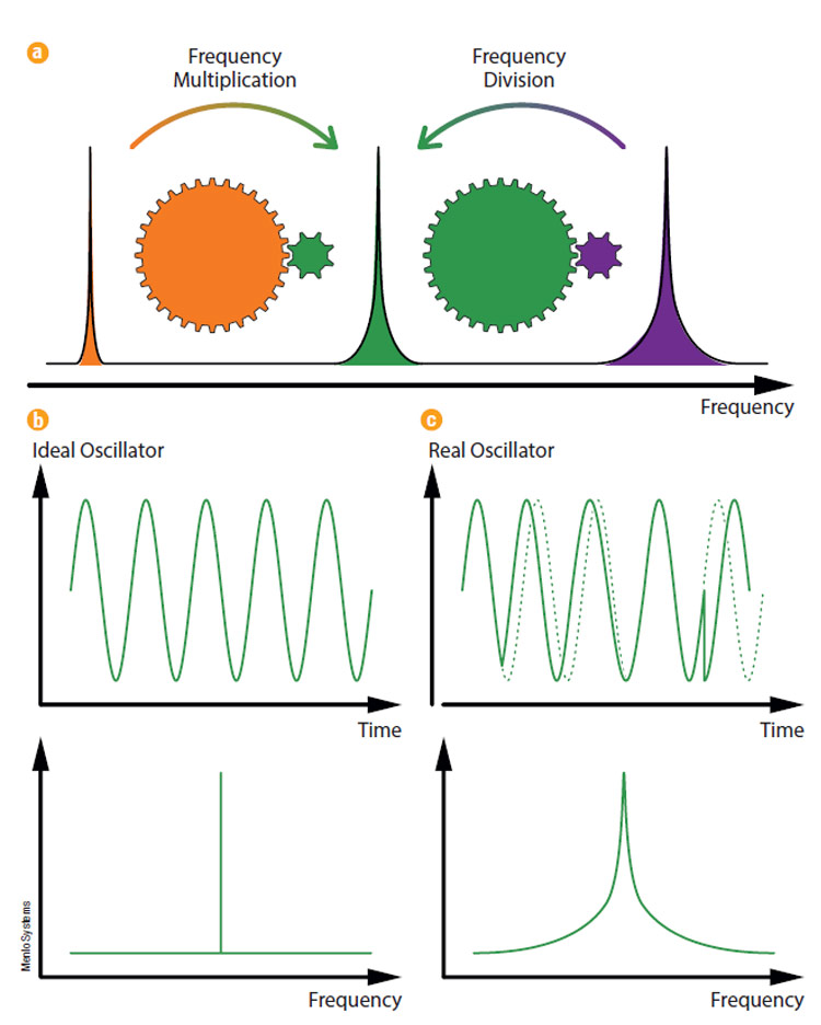
Figure 1. A schematic illustration of frequency synthesis via frequency multiplication and via frequency division (a). Note the opposite scaling of the noise spectrum. A purely sinusoidal output signal generated by an ideal oscillator (b). Viewed in the frequency domain, the output appears as a single narrow spectral line, with all of its power concentrated at a single frequency. In real oscillators (c), frequency fluctuations can arise from both continuous frequency drifts and sudden phase jumps. They appear in the frequency domain as a noise spectrum surrounding the desired pure frequency signal. Courtesy of Menlo Systems.
Early efforts to bridge the optical and RF domains date back to the 1960s. Initial attempts relied on radio-optical systems, which proved to be overwhelmingly complex. Achieving a practical link required decades of research and culminated in a Nobel Prize-winning breakthrough: the optical frequency comb.
Optical frequency combs
An optical frequency comb produces a spectrum of equally spaced light frequencies, resembling the teeth of a comb in the frequency domain (Figure 2). Frequency combs are typically produced using ultrashort, mode-locked lasers. Mode-locking is a form of self-organization among the longitudinal modes of the laser cavity into an ultrashort pulse, ensuring equal frequency spacing and phase synchronization between individual modes. This pulse circulates within the laser resonator at a specific repetition rate (frep). The laser output — a train of ultrashort pulses — is generated by transmitting copies of this circulating pulse through a partially transparent end mirror of the cavity.
Importantly, due to dispersion within the laser cavity, group velocity differs from phase velocity. As a result, from pulse to pulse, the carrier-envelope phase undergoes a slip, and the envelope gradually shifts relative to its carrier wave (Figure 2).
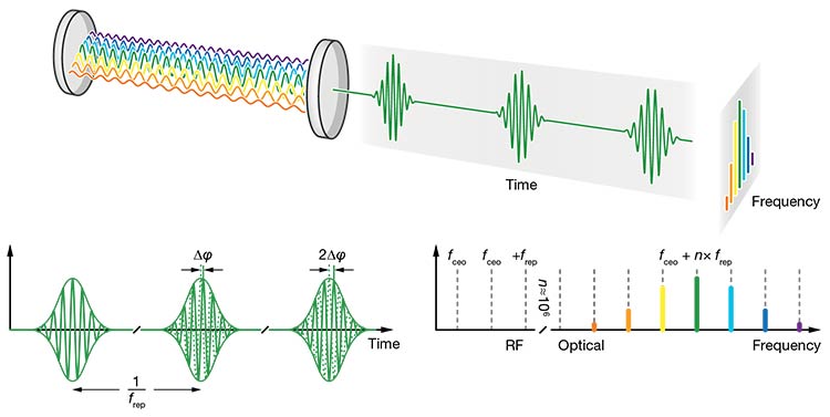
Figure 2. Frequency combs are typically produced by ultrashort-pulsed, mode-locked lasers (top). A periodic pulse train in the time domain (bottom left) corresponds to a series of discrete frequencies in the frequency domain (bottom right), resembling the teeth of a comb. The frequency comb is offset by a certain amount fceo, but otherwise entirely composed of equally spaced frequencies that are separated by the repetition rate frep. RF: radio frequency. Courtesy of Menlo Systems.
In the ideal case, which would be in the absence of external perturbations, the Fourier relationship between the time and frequency domains dictates that a periodic pulse train in the time domain corresponds to a series of discrete frequency modes in the frequency domain. In the frequency domain, the frequencies of the comb are given by:
νn = fceo + n frep
Here, νn is the optical frequency of the n-th comb line; fceo is the carrier-envelope offset frequency; n is an integer index; and frep is the laser repetition rate.
In other words, the frequency comb is offset by a certain amount (fceo, a consequence of the pulse-to-pulse carrier-envelope phase slip), but is otherwise entirely composed of equally spaced frequencies that are separated by the repetition rate frep. This equation establishes a direct link between an optical frequency (νn) and two RF frequencies (fceo and frep). The implications of this relationship are profound, though they can be intuitively inferred.
Optical frequency division
Optical frequency combs uniquely link optical frequencies in the hundreds of terahertz to radio frequencies in the hundreds of megahertz, bridging a frequency gap of up to six orders of magnitude. When operating like a transmission gear, a frequency comb can phase-coherently upconvert an RF signal into an array of evenly spaced optical frequencies. In an inverse mode, acting like a reduction gear, frequency combs can also divide optical frequencies down to the RF domain. As mentioned, this OFD can reduce RF phase noise to levels once thought unattainable.
The approach of locking the frequency comb in two degrees of freedom, effectively anchoring the comb spectrum at both ends, is used to achieve OFD at the highest level of precision (Figure 3). One degree of freedom involves locking the carrier-envelope offset frequency (fceo) to stabilize the lowest-frequency comb tooth. Notably, measuring and stabilizing fceo, also known as self-referencing, posed significant challenges in the early development of optical frequency combs. Octave-spanning frequency combs has enabled a simple yet efficient implementation known as the “f-2f” method. Such octave-spanning frequency combs cover a frequency range more than twice the lowest frequency.
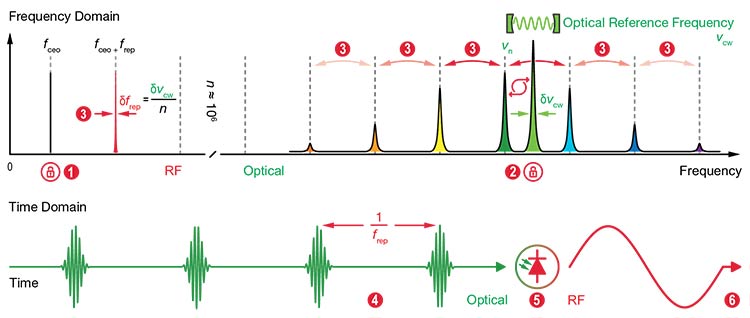
Figure 3. A frequency domain perspective of optical frequency division (OFD) (top).
Locking the carrier-envelope offset frequency (fceo) stabilizes the lowest frequency comb tooth (1). An optical lock of one of the optical comb teeth νn to an external optical reference frequency νcw (2). Pinning the comb spectrum at both ends (fceo and νn) dramatically stabilizes the line spacing (frep) of all of the comb teeth (3). The frequency line spacing will have a frequency stability that is n-times better than the frequency stability of the external optical reference
frequency, with n being on the order of 105 – 106. A time domain perspective of optical frequency division (bottom). A periodic pulse train that has undergone a dramatic reduction in timing jitter (4). The pulse train impinges on a suitable photoreceiver (5). An ultralow-phase-noise RF signal at the repetition rate frequency frep is generated (6). Courtesy of Menlo Systems.
With the lowest-frequency comb tooth pinned, the second degree of freedom is addressed via an “optical lock” of one of the optical comb teeth (νn) to an external optical reference frequency (νcw). The lock operates by continuously measuring νn against the optical reference frequency (via a beat signal), detecting any drift, and applying a feedback loop to keep the comb tooth precisely aligned. As a result, the frequency stability of the external optical reference frequency can be entirely transferred to the comb tooth.
Pinning the comb spectrum at both ends (fceo and νn) stabilizes the line spacing (frep) of all comb teeth. This happens since fluctuations are divided over the frequency spacing between the two pinning points. Switching to the time domain, the periodic pulse train generated by the laser consequently undergoes a dramatic reduction in timing jitter. When such a pulse train impinges on a suitable photoreceiver, it generates an RF signal at the repetition rate frequency (frep) with ultralow phase noise — and the operation achieves OFD.
Considering the beat signal (fbeat) between the optical reference frequency (νcw) and the optical frequency of the n-th comb line (νn),
fbeat = νcw – νn
and inserting for νn from the comb equation gives the relation:
fbeat = νcw – (fceo + n frep)
If the locking is assumed to be “perfect,” fluctuations in fbeat will vanish:
δfbeat = 0
which translates into:
δνcw – δfceo – n δfrep = 0 Rewriting the above equation for fluctuations of the repetition rate gives:
δfrep = (δνcw – δfceo) / n
Since, in practice, δfceo can be brought to zero, the above equation simplifies to:
δfrep = δνcw / n
The fluctuations of the optical reference frequency δνcw are divided down by the mode number n. In other words, the frequency line spacing (respectively the repetition rate frep) will have a frequency stability that is n-times better than the frequency stability of the external optical reference frequency νcw — with n being on the order of 105 – 106.
In summary, OFD serves to lock the electromagnetic field of an external optical reference to a single tooth of an optical frequency comb. This enables the comb to divide it down to an ultrapure RF signal, which is then extracted using optoelectronics. Accordingly, an OFD system consists of three main subunits: an ultrastable optical reference, acting as a flywheel; an optical frequency comb, functioning as a reduction gear; and an RF extraction unit, tailored to the desired RF output frequency.
Each of these components involves intricate details that are themselves refined arts of science. Commercially available integrated ultrastable microwave systems, for example, required years of dedicated R&D and integration engineering. In 2016, a world record for the lowest phase noise on an X-band microwave signal was demonstrated using a laboratory setup1. Building on this success, a fully integrated, transportable prototype was introduced three years later2.
Today, such a system can be compactly housed in rack-mounted, portable devices, making ultrastable microwave sources accessible to a wider range of end users beyond the field of photonics (Figure 4). Unsurprisingly, high-performance radar applications lead the way in adopting and applying the technology.
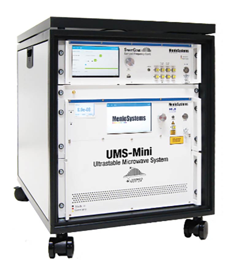
Figure 4. The development of integrated ultrastable microwave systems (UMS) required years of dedicated R&D and integration engineering. Today, these systems can be compactly housed in rack-mounted, portable devices, making them accessible to a wide range of end users. Courtesy of Menlo Systems.
Quantum-enabled radar
Doppler radars exploit the Doppler effect to measure movement by bouncing micro-
wave signals off targets and analyzing frequency shifts in the reflected signals, or echoes. Typically, the frequency reference sources — local oscillators — in these radars also operate at microwave frequencies. Imperfections in local oscillators
introduce phase noise, which can mask weak target echoes. This creates a significant challenge to detecting small, slow-moving objects in the presence of strong clutter — so-called unwanted echoes.
Urban surveillance presents such a challenge: Radars must detect small airborne targets, such as drones, within a cluttered environment.
As the challenge to improve sensitivity
continues to characterize conventional radar technology, the University of Birmingham in England is pioneering a quantum-enabled radar network. The undertaking simultaneously aims to push the limits of radar sensitivity and explore the benefits of radar network synchronization, while leveraging the university’s expertise in ultrastable optical atomic clocks. The full initiative is part of the UK Quantum Technology Research Hub in Sensing, Imaging, and Timing (QuSIT).
Scientists installed a radar testbed
at the university, consisting of two off-the-shelf radars that were modified to replace their conventional internal oscillators with ultrastable microwave systems (UMS) (Figure 5). For an initial proof-of-principle study, each radar cabin was equipped with an individual UMS, capable of self-sufficient operation using its own ultrastable optical reference frequency generator. These generators are continuous-wave lasers that are locked to state-of-the-art ultrastable cavities, routinely achieving subhertz laser linewidths in the optical domain. By OFD, the optical reference frequencies are individually converted into ultralow-phase-noise microwaves and supplied to the radar instruments.
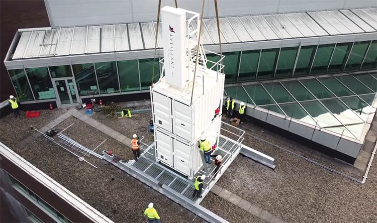
Figure 5. Radar installation on the University of Birmingham campus. The ultrastable microwave system is located in the lower radar cabin. Courtesy of University of Birmingham.
At full expansion, the radar testbed will be entirely interfaced with an optical lattice clock (Figure 6). Such next-generation atomic clocks use ultracold neutral atoms trapped in an optical lattice and achieve unprecedented precision by locking a “clock laser” to an electronic transition of the reference atom, which, in the University of Birmingham test case, is strontium. In this setup, the optical reference frequency for each UMS will be derived from the clock laser of the optical lattice clock, achieving the highest level of precision currently available. Though the effort is highly challenging, early results have been sufficient to drive the project forward3.
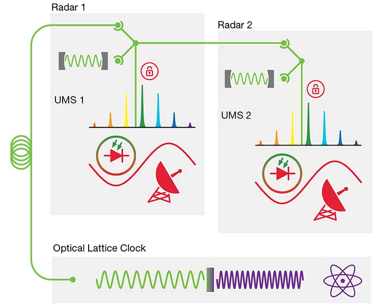
Figure 6. A block diagram depicting aspects of the quantum-enabled radar network, part of the UK Quantum Technology Research Hub in the Sensing, Imaging, and Timing (QuSIT) initiative. For initial proof-of-principle studies, each radar cabin (Radar 1, Radar 2) is equipped with an individual ultrastable microwave system (UMS) capable of self-sufficient operation using its own optical reference frequency generator. At full expansion, the radar testbed will be entirely interfaced with an optical lattice clock, so the optical reference frequency for each UMS will be derived from the clock laser. Courtesy of University of Birmingham.
Outlook
OFD of high-fidelity optical references
generates microwave signals with unprecedentedly low phase-noise levels, with optical frequency combs serving as the unifying link between the optical and RF domains. This concept is only now beginning to reach communities seeking the highest-fidelity RF and microwave signals — some of which have had little interaction with the field of photonics.
Of course, communicating across such industries presents a challenge. More importantly, though, it establishes opportunity for cross-disciplinary enrichment, much like in radar, where ultrastable microwave systems are opening new horizons.
Meet the authors
Jaroslaw Sperling is business developer for Menlo Systems, where he brings a passion for applied photonics and years of experience in ultrafast lasers. He holds a Ph.D. in physical chemistry from the University of Vienna; email: j.sperling@menlosystems.com.
Michele Giunta leads the Ultrastable
Photonic Microwaves group at Menlo Systems. He has been deeply involved since the early days of development and brings unwavering dedication to advancing the field of photonic microwave oscillators; email: m.giunta@menlosystems.com.
Mohammed Jahangir is lead senior research fellow at the University of Birmingham in England. With nearly 30 years of experience
in surveillance systems for defense and civil sectors, he leads the development of a quantum-enabled networked staring radar; email: m.jahangir@bham.ac.
Acknowledgments
The authors wish to acknowledge Benjamin Sprenger of Menlo Systems GmbH and Jason Reeves of Menlo Systems Inc. for their
valuable input and assistance in preparing this article.
References
1. X. Xie et al. (2016). Photonic microwave signals with zeptosecond-level absolute
timing noise. Nat Photonics, Vol. 11,
pp. 44-47.
2. M. Giunta et al. (2020). Compact and
ultrastable photonic microwave oscillator. Opt Lett, Vol. 45, p. 1140.
3. M. Jahangir et al. (2024). Development of a networked photonic-enabled staring radar testbed for urban surveillance. IET Radar Sonar Navig, Vol. 18, No. 1, pp. 41-55.
/Buyers-Guide/Menlo-Systems-GmbH/c9311
/Buyers-Guide/Menlo-Systems-Inc/c19048