The integration of CO2 lasers and galvanometer-based scan heads presents technical challenges. Optimizing alignment parameters holds the key to maximizing efficiency.
By Julia Janik
Due to their high efficiency and versatility, CO2 lasers are widely used for various applications in the industrial, medical, and scientific sectors. These lasers typically operate at a wavelength of
10.6 µm in the infrared spectrum. This wavelength is particularly effective for cutting, engraving, and marking materials, such as glass, ceramics, plastics, and wood.
Aside from selecting the optimal laser for a target application, it is crucial for users to ensure that the laser beam is precisely delivered to the material. A scan
head, which uses two galvanometer mirrors to steer the laser beam across the material surface in the x and y directions, is one of the most common methods for directing and steering the beam.
Scan heads are effective for applications beyond material marking, in areas such as cutting, drilling, and 3D printing applications. Certain applications heighten the importance of precisely matching the laser and the corresponding scan head. The exact alignment of this combination is paramount to achieve the best possible performance: a stable focus and effective marking quality over the whole scanning field.
CO2 laser marking of glass is one such application. This process involves creating stress-relieved marks using a small focus spot size between 100 and 300 µm. The laser beam rapidly heats and cools the glass surface, causing microfractures that form visible marks (Figure 1). Sharp temperature differentials can lead to larger, inconsistent fractures, and gradient differentials can create smaller, consistent fractures. For high-speed marks, using a dashed line can improve mark consistency by encouraging the system to make secondary parallel fractures. Pulsed lasers are particularly effective for this method. Large or out-of-focus spots >300 µm
create a controlled continuous fractured look, requiring slower scan speeds due to the low energy density.

Figure 1. Laser marking with a CO2 laser and an optimized scan head is performed on standard glassware (top) and architectural glass (bottom). Courtesy of Novanta.
Of course, depending on the application, an end user may desire different results or geometries for these marks. Therefore, the focus size must be carefully selected and stabilized to ensure consistent microfractures, leading to accurate and homogeneous marks.
Selecting the right CO2 laser and scan head is crucial to achieve a consistent focus over the whole marking field. Further, the subsequent integration of both components must be precise. Users must select the optimal mechanical, electrical, and optical components, and ensure that the design of the optical beam path is robust and cost-effective.
Though textbook solutions exist for many integration problems, these fixes are often expensive, time-consuming, and complex. Fortunately, many preemptive approaches are available to end users to ensure reliable and consistent operation.
Matching beam and scan head
A user must consider several parameters,
including wavelength, collimation, ellipticity, mode, size, and input angle, to accurately match the incoming laser beam to the scan head and ensure optimal scan head performance. The user must first confirm that the laser input beam is within the wavelength range of the coating on the optics in the scan head. Then, the user must select and match the laser beam diameter to the scan head’s clear aperture.
Generally, larger scan head apertures enable smaller focal spot sizes and accommodate higher laser powers. Accordingly, smaller apertures facilitate faster and more dynamic beam manipulation. Because smaller scan heads are often more affordable than larger versions of these components, it is necessary to ensure that the laser’s maximum power output (Pmax) is compatible with the scan head’s mirror aperture size (D) and mirror reflectivity (R) performance (Equation 1).
In Gaussian optics, for example, the initial beam size significantly influences the focus spot size produced by a scan head. Ideally, the clear aperture of the scan head would be used with the largest diameter beam to attain the smallest focused spot size (Figure 2). Laser beam width is typically reported as the 1/e2 diameter; this value represents the point at which the beam intensity falls to ~13.5% of its peak value. This should be compared with the scan head’s effective clear aperture, which is available in the product or system datasheet.
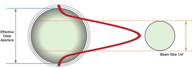
Figure 2. In Gaussian optics, initial beam size partially determines the focused spot size produced by a scan head. Laser beam width is reported as the 1/e2 diameter, representing where beam intensity falls to ~13.5% of its peak value. Here, the comparison of an effective clear aperture is made to 1/e2 beam size. Courtesy of Novanta.
To ensure that 99% of the laser beam’s energy passes through the scan head, a safety factor of ~1.5× should be applied between the beam size — given as the 1/e2 value — and the clear aperture (Equation 2).
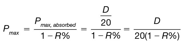
Equation 1. A representation of the relationship between the maximum power (Pmax) output of the laser and the scan head performance. Pmax must be compatible with the scan head’s mirror aperture size (D) and mirror reflectivity (R). Courtesy of Novanta.
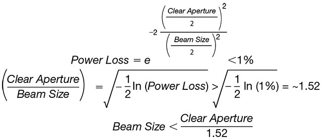
Equation 2. A calculation of the power loss and ratio for Gaussian beams. To ensure that 99% of the laser beam’s energy passes through the scan head, this calculation indicates that a safety factor of ~1.5× should be applied between the beam size — given as the 1/e2 value — and the clear aperture. Courtesy of Novanta.
A clear aperture-to-beam diameter ratio of <1.5× may cause meaningful diffraction rings and laser power loss within the system, which could result in reduced marking or cutting performance and shorter component lifetimes. Conversely, a higher ratio will increase power density on the optical components and produce a larger spot size in the focal area.
To obtain the desired beam size, a user must select an adjustable beam expander with the correct expansion ratio. Beam expanders are critical to achieve desired performance, ensuring both effective beam shaping and size control. The ideal solution, in terms of performance, is a zoom beam expander that covers a wide range of expansion ratios, which a user can adjust to achieve necessary beam size.
However, this type of beam expander is highly complex and expensive. And, largely due to their complex design, these expanders are generally more sensitive to external influences such as shock, vibration, and temperature changes. Using a commonly available beam expander that produces a beam size as close as possible to the ideal input beam is a solution that balances cost-effectiveness and robust performance.
Implementing these considerations and tailoring the system and components to the target application should deliver predictable performance and optimal results (see sidebar and table at end of article).
Aligning the laser
The optical axis, an imaginary line through the center of the scan head’s input aperture, is essential for aligning all components to ensure high-quality results. Misalignment can cause off-center beam outputs, power loss, and/or degraded scan field performance.
CO2 lasers often vary in beam exit location and angle. This requires the precise alignment with scan heads. This alignment, involving both angular and translational adjustments, is complex. Any misalignment in the beam input will be amplified in the optical far field, leading to degraded process performance and nonoptimal results.
The standard approach for laser alignment in free-space optics is the use of two individual mirrors on kinematic mounts and two targets as reference points. This configuration enables both lateral and angular alignment of the beam into the scan head aperture (Figure 3). This approach may also support different mirror configurations, depending on the available space and the position of the laser and scan head.
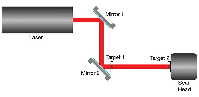
Figure 3. A typical setup used to align a CO2 laser into a scan head aperture. Courtesy of Novanta.
Since CO2 lasers emit invisible infrared radiation, the beam must be visualized at the target. A common solution is to use a wire-mesh mode screen that glows at the beam contact point when sufficient power is applied. The hole in the center of the mesh is designed to allow the beam to be precisely centered in the target. Using a crosshair target, with a piece of thermal paper to mark the position of the beam at low power, is one simple alternative to the wire-mesh method.
In theory, laser alignment methods, including the example in Figure 3, offer highly accurate solutions. However, these architectures assume perfect conditions and a stable environment, and they often carry significant investments of costs and time. Most industrial environments will not be suitable for such textbook solutions. Companies must balance precision with cost-efficiency in most cases, and a slightly less precise but more practical solution is often preferable and more financially viable.
Additionally, for these setups to support optimal performance, each laser can have only a slightly different beam path. This makes it impossible to rely on a fixed, one-size-fits-all design. Instead, alignment systems must be flexible enough to account for these small variations to ensure consistent performance.
Laser and scan head control
In addition to the optomechanical design, users seeking to maximize the performance of the laser and scan head subsystem must also consider the conditions needed for seamless laser and scan head control. For the best possible system performance, a user must streamline communication between laser, scan head, and controller. The usability of the software is another core parameter that must be controlled.
When pairing a scan head with a controller, the scan head’s specifications
— such as field size, speed, and accuracy — should be matched with the capabilities of the controller. For example, high-speed applications may require a controller to support rapid signal processing and feedback. Larger mirrors, on the other hand, may demand more powerful control signals to maintain accuracy at high speeds.
Fundamentally, the scan head and controller should be compatible and use the same communication protocol — for example, XY2-100 or SL2-100. Certain scan heads require specific calibration software or offer bidirectional communication protocols. In these cases, the controller must support these features. To simplify this challenge, users should select a scan head and controller that support several common communication protocols, and select one communication protocol that supports bidirectional communication to serve as their standard.
The controller must also synchronize the scan head with the laser and properly time the signals to avoid distortions. A controller with precisely timed laser controls that optimize synchronization between scan heads and lasers should enable users to bypass delays. The implementation of real-time scanning feedback controls can further improve system performance.
Finally, although complex software interfaces can be difficult to use, and may therefore increase the risk of errors, many user-friendly software options exist on the market. These solutions integrate seamlessly into the hardware and simplify operations. Software that supports integration with various hardware components, such as vision systems, positioning systems, and conveyor belts, further enhances automation and improves overall system productivity.
Keeping all these factors in mind can be challenging, especially if the components are sourced from different suppliers and have different specifications. In application, though, these measures help to ensure the development of a well-matched and high-performance system.
Thermal management considerations
For CO2 lasers, the laser gas mixture gain decreases as the gas heats up, resulting in a loss of output power. Maintaining a stable laser temperature provides the best output power stability. The gas mixture is driven with either direct current or radio frequency energy to cause the mixture to emit photons and develop the laser beam. These electronics generate a significant amount of heat that must be carefully removed to prevent damage to the components.
This logic applies to all industrial laser types: Overheating can reduce the lifetime of components and increase the risk of equipment failure. Even before overheating occurs, simple fluctuations in temperature are apt to negatively affect a lasers’ output power, beam quality, and stability.
Although not all scan heads are actively cooled, cooling their components — mirrors and/or galvanometers, for example — can improve system performance. Galvanometer cooling increases the stability of scan head performance and minimizes temperature drift. This is important for high-duty-cycle, full-speed, and full-range applications that require exceptional accuracy.
The challenge with the mirrors is that despite their highly reflective coating, the components are still affected by a hot spot where the laser beam gets reflected. Cooling the galvanometer mirror reduces the heat, and, therefore, the degradation of the coating, which over time can lead to overheating and sudden failure.
Passive cooling via heat dissipation is sufficient for many low-power laser systems, whereas systems that achieve an output power of >100 W require water cooling. This option is the most efficient to remove heat and provide a stable operating environment. Most water-cooled systems use a closed-loop circuit with a chiller.
Users should base the selection of a suitable chiller on a combination of factors, including the required cooling capacity, flow rate, pressure limits, and tubing design. Chillers must meet flow rate requirements to offer enough cooling capacity to absorb the heat load, and the minimum flow rate of the system must be covered, while not exceeding the maximum pressure.
Additional subsystem factors
CO2 lasers are Class 4 lasers; they are therefore governed by a well-established set of laser safety protocols. To limit the risk of injury or system damage, enclosing the laser system as well as possible and covering all beam paths is paramount. Additionally, the laser system should be integrated into the machine safety with an interlock and emergency stop mechanism to shut down the system immediately in case a door is opened or in the event of an emergency situation. And, since the laser process can create harmful fumes that may cause injury to the machine operator and pose a fire or explosion risk, proper fume extraction, with the right filter material, is needed to maintain machine safety.
Especially for free space systems, with multiple alignment mirrors, these requirements can become complex and carry high costs. Nevertheless, users must maintain compliance with local regulations for industrial laser safety such as OSHA, ANSI Z136, and IEC 60825.
The seamless integration of the laser system with other machines for automation and procession is another consideration. For certain industrial applications, the controller and software must communicate with existing vision systems, positioning systems, and/or conveyor belts, for example. Industrial communication interfaces such as Ethernet/IP, RS-232, Modbus, and input/output connectivity are important to support integration.
Also, since the power supply must be compatible with the laser model and its operational requirements, users must be sure to correctly select the appropriate power supply element. The user and/or system integrator must match voltage and current needs while considering that the power requirements for scan heads and controllers are lower compared to those of the laser. Scan heads and controllers can have similar power requirements, and so both components in an optimized system could share one power supply to reduce complexity and cost.
Ensuring lasting performance
Accurate optical matching of the laser beam and scan head aperture is essential to achieve optimal system performance (Figure 4). Still, additional variables must be considered to ensure user safety and limit system damage. Though achieving
the ideal integration scenario may be challenging, systematically approaching the selection of the right components and the implementation of all necessary practices can significantly enhance performance and ensure high-quality results.
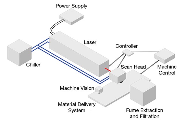
Figure 4. A complete illustration of a laser and scan head system. Courtesy of Novanta.
Meet the author
Julia Janik, Ph.D., formerly an application
engineer and laser engineer at Novanta, has more than 10 years of laser experience and serves as project manager for Central Applications and Subsystems at the same company; email: julia.janik@novanta.com.
Spotlight on Laser Beam Expanders
For a scan head with a 14-mm clear aperture and a CO2 laser with a 2.5-mm beam diameter (1/e2), the ideal beam size, as calculated using Equation 2 (above in article),
is 9.2 mm. The table shows commonly available beam expanders and their
corresponding beam sizes. Using the table values, a 3.5× beam expander is
the optimal choice, because it most closely matches the ideal diameter without being excessively large.
Commercial Beam Expanders: Effects of Ratios on Beam Sizes
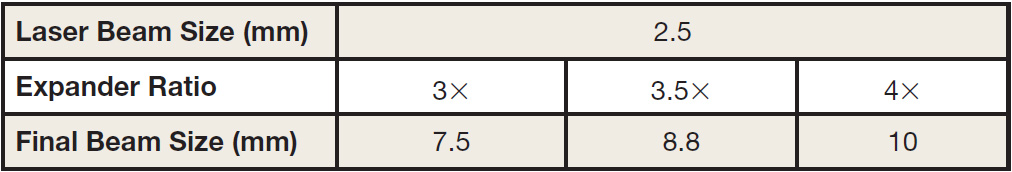
Courtesy of Novanta.