Stray light can impede the performance of any optical system. With a deeper understanding of stray light, and the right tools, optical engineers can predict and compensate for its effects in order to improve quality.
Richard Pfisterer, Photon Engineering LLC
Electrical engineers are very familiar with the effects of shot noise, thermal noise, flicker noise and crosstalk, and recognize how these effects can reduce the signal-to-noise ratio (SNR) in their systems.
Most optical engineers, on the other hand, frequently fail to appreciate the effects of optical noise in their systems, leading to non-optimal performance. This can be particularly significant in astronomical observations, low-light level signal detection and medical imagery, where every signal photon counts. Furthermore, optical engineers may not understand how stray light propagates through their systems or how optical surfaces and painted baffles scatter light. Fortunately, the field of stray light analysis is mature, the software is capable and our understanding of scatter processes continues to grow. Today, the tools and understanding needed to predict stray light levels, identify sources of stray light, and confidently recommend design/implementation changes to improve the quality of the optical instrument exist.

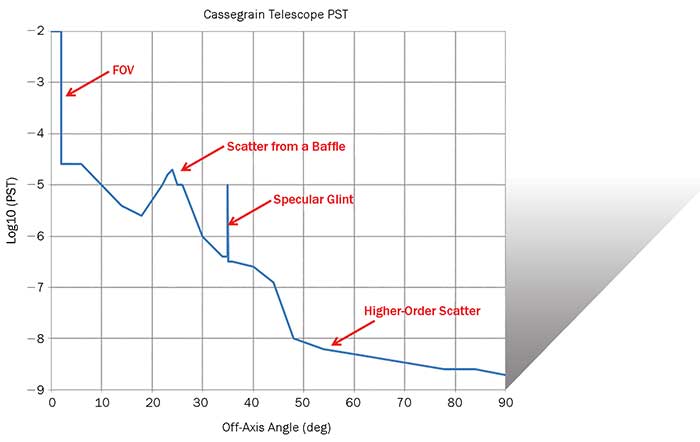
Figure 1. A plot of the point source transmittance (PST) can graphically indicate scatter from internal structures, specular glints and higher-order scatter effects. Courtesy of Photon Engineering LLC.
Sources of optical noise
Diffraction is considered a stray light mechanism because it produces a distribution of energy that extends well beyond what would be expected from geometrical considerations; for example, a circular aperture, when illuminated by coherent light, produces an Airy distribution that can cover the area of the detector. Since diffraction irradiance is proportional to the wavelength of light, it is rarely a significant stray light contributor in the UV and visible, but can become very significant in the longwave IR, dominating the effects of optical surface scatter.
Ghost images can result when light incident on a surface is divided into reflected and transmitted components and both continue to propagate; ultimately some portion of the light reaches the image plane. Since ghost images are specular, they can retain coherence and polarization properties of the incident light; it is not uncommon in high-powered laser systems for ghost images to sum coherently to produce high fluence levels capable of shattering an optical element.
Diamond-turned surfaces that are not post-polished typically contain residual periodic grooves left over from the turning process that can act like a diffraction grating. Incident light is diffracted into multiple unintended orders that propagate through the system.
The grinding and polishing processes leave a residual microroughness on an optical surface as well as subsurface damage. A small amount of the light incident on an optical surface is scattered into an angular (typically Lorentzian) distribution centered on specular direction and continues to propagate. At the image plane, the scatter distributions from all of the surfaces add incoherently to create a composite scatter field.
Dust, with its ability to scatter light, is ubiquitous in virtually all environments. The exact distribution of scattered light is a function of the wavelength of light, the complex refractive indices of the particulates and their size population on the surface. While totally unrelated mathematically to surface roughness, particulate scatter distribution is also manifest as a Lorentzian function.
Recognizing the very wide variation in composition, it is not surprising that paints and surface treatments — such as anodization or texturing — can produce very diverse distributions of scattered light. Analysts classify paints and surface treatments into four broad categories: diffuse (matte) finishes, specular (glossy) finishes, hybrid finishes that can vary from diffuse to specular depending upon the angle of incidence of light onto the surface, and “other,” which includes carbon nanotube technology, the “blackest” materials that we know of. Paints and surface treatments can be very effective at controlling stray light but they can also cause unwanted side effects such as outgassing and particulate generation (flaking).
All structures radiate thermal energy according to their temperatures and emissivities. However, the magnitude of this thermal radiation is usually significant only in the longwave IR (8 to 12 µm) where the peak of the blackbody curve corresponds to room temperature. Unfortunately this is exactly where many types of instruments operate, so designers of thermal IR seekers, medical imaging devices — for breast and skin cancer diagnoses, for example — and other thermal detection systems must consider how the thermal self-emission of the instrumentation can degrade the contrast of the thermal signal they are trying to image.
Stray light metrics
Just as a lens designer might use encircled energy or root-mean-square (rms) wavefront error to characterize the performance of an optical system, stray light analysts use several different metrics for describing the stray light characteristics of an optomechanical system.
Point source transmittance (PST) is the oldest stray light metric dating back to the 1970s and is conceptually very simple: Following from linear system theory, PST is simply the ratio of some measure of energy on the detector to the energy incident into the system, as a function of angle of incidence. This very general definition is frequently made more specific by expressing the PST as the ratio of the irradiance incident on the detector to the irradiance incident on the entrance aperture. Regardless of the definition, the PST has value as a diagnostic tool — by identifying at which angle(s) stray light effects become significant, which leads to the recognition of the responsible stray light mechanism(s) — as well as a comparative tool. By comparing the PSTs of two different systems, the analyst can immediately quantify how the hardware differences affect the stray light characteristics.
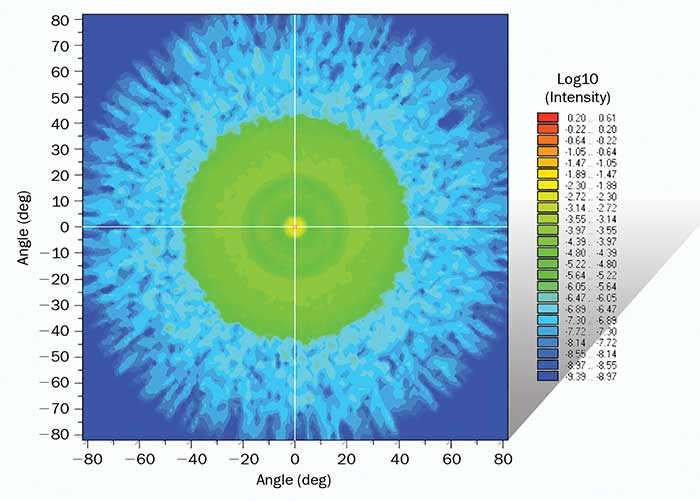
 Figure 2. A plot showing the percentage stray light calculation as an intensity plot in object space. Courtesy of Photon Engineering LLC.
“Percent stray light” captures the stray light characteristics of a system as a single number; it is the ratio of the optical noise power from every conceivable stray mechanism to the signal power from the intended target. In other words, it is essentially the reciprocal of SNR expressed as a percentage. In a well-baffled system, the percent stray light is typically on the order of a few percent. This particular stray light metric is commonly used in applications such as orbiting Earth-resource satellite cameras where the field-of-view is very small and the Earth as a stray light source subtends a large solid angle.
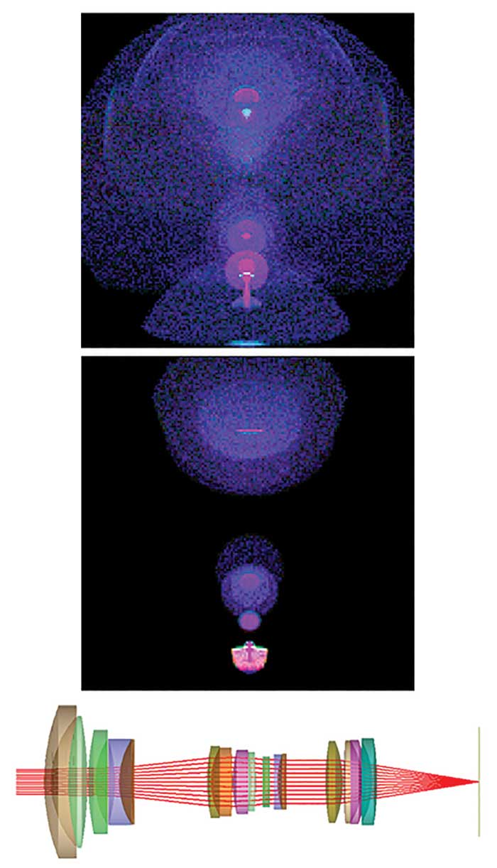
Ghost image calculations are very often used in the development of photographic and cellphone lenses to identify “sensitive” surfaces that can cause artifacts when illuminated under specific conditions. The calculation, while ray intensive, is straightforward and can include the effects of source spectral bandwidth, coating sensitivity to variations in angles of incidence on each surface, material absorption, detector responsivity and so on.
In longwave-IR imagery applications, the thermal self-emission is calculated using a clever approach developed in the 1980s: Rays traced backward from the detector determine the geometrical configuration factor (GCF) — the projected solid angle divided by pi — for each component. Once the GCF is known, standard radiometric equations can be used to determine the thermal self-emission contributions usually reported in watts or photons/area/sec. The tremendous advantage of this technique relative to previous ones is that the accuracy of the calculation is determined by the number of rays traced, which is decided by the analyst.
Baffles design
Baffles, stops, and vanes all work to control the propagation of unwanted light through an optical system. Most optical designers are familiar with field stops to block out-of-field stray light; however these are not always effective in reflective systems where the optical path “folds” onto itself. Lyot stops are stops placed in a conjugate plane to the entrance pupil and are used primarily to block diffraction effects originating from the edge of the pupil.
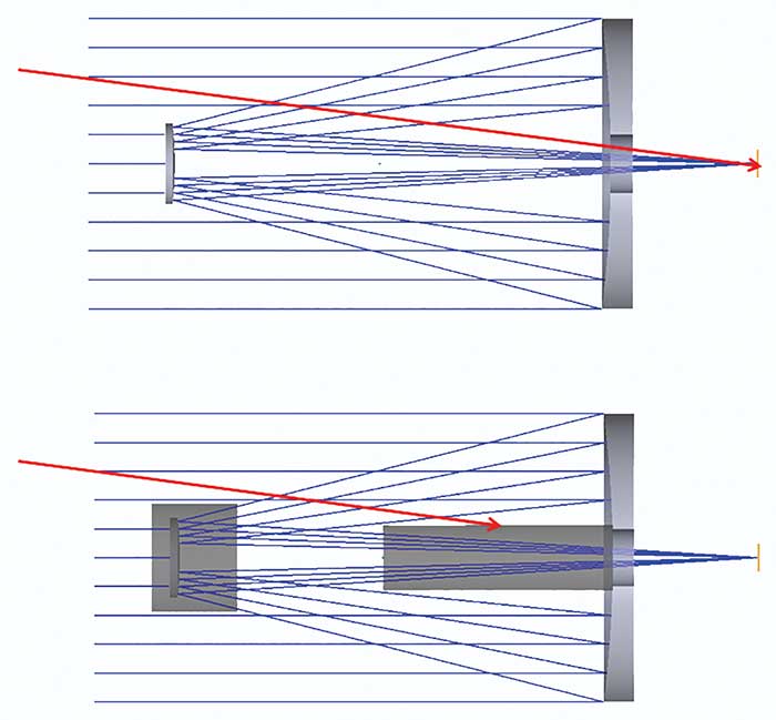
Baffles tubes containing vanes are commonly used to shadow an optical system from direct illumination at high off-axis angles and to control the number of scatter events prior to light reaching the optical system. (Since scatter is an inefficient method of energy propagation, sometimes it only takes a few interactions of stray light with vanes along a baffle in order to adequately suppress the stray light.) They are also used in dewars and other detector assemblies to limit illumination of the detector from stray light.

Figure 3. The morphology of a ghost can change dramatically over the field of view of a system. Upper plot: polychromatic ghost image at 41° off-axis, Middle plot: polychromatic ghost image at 47° off-axis, Lower plot: Axial ray trace of camera optics. Courtesy of Photon Engineering LLC.
Not all vanes are overt. Sometimes a very shallow vane is used to suppress a grazing incidence reflection off of the side of a telescope tube.
Rarely is there a single best or optimum approach to baffle implementation in a real-world system. Baffles add weight and cost to a system, and stray light control is simply one of many considerations when building hardware.
Capabilities of modern analysis software
Modern stray light analysis software has benefited from almost 40 years of continual development and comparisons with actual hardware, and has therefore matured greatly. In many ways, the software is very much like commercial CAD software in that it can define and subsequently edit complex geometries. Unlike lens design software that typically describes systems with, say, fewer than 100 surfaces, stray light analysis software may need to describe hundreds of thousands of surfaces literally modeling each “nut and bolt.”
Where stray light software departs from CAD is in the specification of the specular and scatter properties of the components. In order to perform even the most rudimentary stray light calculations, the optical coating (specular) information must be specified as well as the scatter models; the latter are described by BSDFs (bi-directional scatter distribution functions). BSDFs can become extremely complex to define as they are functions of both 3D specular and scatter angles, and frequently there are additional dependencies on wavelength and polarization. Finding a complete specification of the BSDF of a paint or surface treatment in the open literature is oftentimes impossible and so it is common to send samples to measurement laboratories that have multiwavelength scatterometers to characterize the BSDF.
A single ray incident on a surface assigned an optical coating will generally create two rays: a reflected ray and a transmitted ray whose fluxes are determined from the properties of the coating, the wavelength and polarization of the ray, and the ray’s angle of incidence with the local surface normal. This process is called “ray splitting” and is the basis of all ghost image calculations.

Figure 4. Sometimes light does not propagate the way the lens designer intended. Baffles can prevent unwanted light from reaching the detector. Courtesy of Photon Engineering LLC.
A single ray incident on a surface assigned a scatter model will generate a distribution of scattered rays whose flux values are determined by the BSDF. While scatter physically radiates into 2π sr relative to the local surface normal, it is computationally inefficient to generate scattered rays in software into so large a scatter angle. Consequently scattered rays are typically “aimed” into specific directions of interest, such as toward a detector or image of a detector. This is referred to as “importance sampling”.
Once the geometry is defined and the specular and scatter models (including importance sampling) are specified, performing a stray light calculation involves defining a source with the correct radiant, spectral and coherent properties and then propagating those rays nonsequentially through the system. Various thresholds are set so that rays whose fluxes drop below some predetermined level are terminated. Given the complexity of the systems and the number of rays ultimately traced, it was not uncommon for a given calculation to run for several hours, several days, or even longer. However, in recent years, the accessibility of distributed computing networks and the development of GPU-enabled ray trace software have made it possible to tremendously reduce the run times of stray light calculations. Using PCs with high-end GPU boards, stray light analysts can now trace billions of rays through non-trivial optomechanical systems in a matter of minutes.
In the early days of stray light analysis, the sole output of a lengthy calculation was a single number: the total stray light level on the detector. While this was certainly useful information, it didn’t suggest to the analyst what needed to be done to make the system perform better. However with modern stray light software, the analyst has access to numerous calculations that can provide insight into how stray light is propagating. For example, in addition to irradiance plots of the signal and stray light at the detector, the analyst can peruse tables of individual surface stray light contributions, lists of ray paths that describe the exact trajectories of stray light through the system, and graphical representations of how surfaces are illuminated. Based on these outputs, the analyst can decide which surfaces require better baffling, upgraded AR coatings, a different type of paint and so on. Hamming’s oft-quoted statement that “the purpose of computing is insight, not numbers” very much describes the value of modern stray light software1.
Under the relentless pressure to make optomechanical systems smaller yet more sensitive, instrument designers, systems engineers, and stray light analysts work to make every photon useful. While there are theoretical limits on how smooth a surface can be manufactured or how black a paint can be, very often extreme measures are not required to make a system work. Sometimes it is simply a matter of correctly positioning a single vane in a baffle or keeping internal surfaces “clean enough” that makes the difference between unacceptable and near-optimum performance.
Reference
1. Hamming, Richard (1962). Numerical Methods for Scientists and Engineers. New York: McGraw-Hill. ISBN 0-486-65241-6.