A mirror is an important element in many optical systems. Its basic function is to redirect light, often with the purpose of making an optical system more compact. This article discusses the kinds of thin-film coatings that can be used for mirrors. The choice of coating depends on the application, including the spectral range of interest, the optical wavefront quality desired and the cost limitations.
JDSU
The basic difference between the household mirror and the optical mirror is that one is coated on the back surface and the other is coated on the front. For optical applications, a front-surface mirror must be used. This means that the reflective surface is subject to environmental degradation, even though it is usually in an enclosed environment and not exposed to the harsh conditions of the household mirror. An important part of mirror technology is providing a durable front-surface mirror that is stable and can be cleaned.
A mirror’s substrate surface should be flat and smooth. The flatness is usually specified in terms of how many wavelengths of light the surface deviates from being a perfect plane. For many applications, the glass can be flat to a few wavelengths of visible light. For the most stringent applications, the surface must be flat to a quarter of a wavelength or less. The surface quality of a mirror, or its smoothness, is measured in terms of scratches and digs that are still present after polishing. A scratch/dig specification of 80/50 is fairly routine, while a specification of 20/10 is much better, but more expensive.
For some applications, a mirror’s ability to conduct heat is important. In these cases, metal substrates are often used because metal is much more conductive than glass. Optical-quality metal surfaces can be fabricated by polishing or single-point diamond turning. The most common metals used are copper and aluminum. Although beryllium is highly toxic, it is used when especially light weight, stiff mirrors are required. In the case of metal substrates, the coating improves the reflectance and makes the surface more durable and resistant to scratches.
Metal mirror coatings
The simplest and most common mirror coating is a thin layer of metal. A 100-nm layer of aluminum or silver makes an excellent reflector for the visible spectrum. Aluminum reflects about 90 percent of the light across the visible spectrum, while silver reflects about 95 percent. The reflectance of a metal mirror can be calculated from the index of refraction n and the extinction coefficient k of the metal. The reflectance of a metal surface in air is given by:

An extensive list of n and k values over a wide range of wavelengths and for many metals is available.1,2,3 Table 1 contains an abbreviated list, with data given for ultraviolet (0.2 and 0.3 μm), visible (0.4 to 0.7 μm) and infrared wavelengths (1 to 10 μm). In general, metals with k>>n are shiny, while those with k ≈ n ≈ 3 are gray. Thus, silver with n = 0.13 and k = 2.92 at 0.5 μm is shiny, while tungsten with n = 3.4 and k = 2.69 is not. As the wavelength increases into the IR region, n and k increase, leading to high reflectance in this spectral region.
TABLE 1.
n AND k FOR SELECTED METALS
|
Wavelength (µm):
|
|
0.2 |
|
0.3
|
|
0.4 |
|
0.5 |
|
0.6 |
|
0.7 |
|
1.0 |
|
2.0 |
|
4.0 |
|
10.0 |
| |
|
|
|
|
|
|
|
|
|
|
|
|
|
|
|
|
|
|
|
|
Aluminum* n:
k:
|
|
0.12
2.30 |
|
0.28
3.61 |
|
0.49
4.86 |
|
0.77
6.08 |
|
1.20
7.26 |
|
1.83
8.31 |
|
1.35
9.58 |
|
2.15
20.7 |
|
6.43
39.8 |
|
25.3
89.8 |
| |
|
|
|
|
|
|
|
|
|
|
|
|
|
|
|
|
|
|
|
|
Beryllium n:
k:
|
|
0.84
2.52 |
|
2.42
3.09 |
|
2.89
3.13 |
|
3.25
3.17 |
|
3.43
3.18 |
|
3.47
3.25 |
|
3.28
3.87 |
|
2.44
7.61 |
|
2.38
16.7 |
|
8.3
41.0 |
| |
|
|
|
|
|
|
|
|
|
|
|
|
|
|
|
|
|
|
|
|
Chromium n:
k:
|
|
0.89
1.69 |
|
0.98
2.67 |
|
1.50
3.59 |
|
2.61
4.45 |
|
3.43
4.37 |
|
3.84
4.37
|
|
4.50
4.28 |
|
4.01
6.31 |
|
3.08
13.7 |
|
14.2
27.5 |
| |
|
|
|
|
|
|
|
|
|
|
|
|
|
|
|
|
|
|
|
|
Copper n:
k:
|
|
1.01
1.50 |
|
1.39
1.67 |
|
1.18
2.21 |
|
1.13
2.56 |
|
0.40
2.95 |
|
0.21
4.16 |
|
0.33
6.60 |
|
0.85
10.6 |
|
2.41
21.5 |
|
11.6
49.1 |
| |
|
|
|
|
|
|
|
|
|
|
|
|
|
|
|
|
|
|
|
|
Gold n:
k:
|
|
1.43
1.22 |
|
1.80
1.92 |
|
1.66
1.96 |
|
0.85
1.90 |
|
0.22
2.97 |
|
0.16
3.95 |
|
0.26
6.82 |
|
0.85
12.6 |
|
2.60
24.6 |
|
12.4
55.0 |
| |
|
|
|
|
|
|
|
|
|
|
|
|
|
|
|
|
|
|
|
|
Molybdenum n:
k:
|
|
0.81
2.50 |
|
2.86
3.70 |
|
3.03
3.22 |
|
3.41
3.74 |
|
3.68
3.47 |
|
3.82
3.56 |
|
2.58
4.02 |
|
1.38
10.4 |
|
2.32
23.0 |
|
12.6
56.7 |
| |
|
|
|
|
|
|
|
|
|
|
|
|
|
|
|
|
|
|
|
|
Nickel n:
k:
|
|
1.00
1.54 |
|
1.74
2.00 |
|
1.61
2.36 |
|
1.68
2.96 |
|
1.88
3.54 |
|
2.18
4.05 |
|
2.81
5.00 |
|
3.78
8.17 |
|
4.15
14.6 |
|
6.83
37.0 |
| |
|
|
|
|
|
|
|
|
|
|
|
|
|
|
|
|
|
|
|
|
Platinum n:
k:
|
|
1.24
1.34 |
|
1.46
2.17 |
|
1.72
2.84 |
|
1.97
3.44 |
|
2.25
3.97 |
|
2.54
4.49 |
|
3.44
5.79 |
|
5.27
6.72 |
|
3.74
15.5 |
|
10.4
38.0 |
| |
|
|
|
|
|
|
|
|
|
|
|
|
|
|
|
|
|
|
|
|
Rhodium n:
k:
|
|
0.78
1.85 |
|
0.84
3.00 |
|
1.41
4.20 |
|
1.88
4.68 |
|
2.07
5.37 |
|
2.33
6.11 |
|
3.41
7.83 |
|
3.83
13.1 |
|
5.71
25.1 |
|
14.4
57.3 |
| |
|
|
|
|
|
|
|
|
|
|
|
|
|
|
|
|
|
|
|
|
Silver n:
k:
|
|
1.07
1.24 |
|
1.51
0.96 |
|
0.17
1.95 |
|
0.13
2.92 |
|
0.12
3.73 |
|
0.14
4.52 |
|
0.21
6.76 |
|
0.65
12.2 |
|
2.30
24.3 |
|
13.3
54.0 |
| |
|
|
|
|
|
|
|
|
|
|
|
|
|
|
|
|
|
|
|
|
Tungsten n:
k:
|
|
1.47
3.24 |
|
2.98
2.36 |
|
3.39
2.41 |
|
3.40
2.69 |
|
3.56
2.85 |
|
3.84
2.88 |
|
3.04
3.44 |
|
1.28
7.52 |
|
1.77
17.6 |
|
9.5
45.0 |
*Aluminum has a reflectance dip at 0.8 µm: for λ = 0.8 µm, n = 2.80 and k = 8.45
for λ = 0.9 µm, n = 2.06 and k = 8.30
SOURCE: Handbook of Optical Constants of Solids
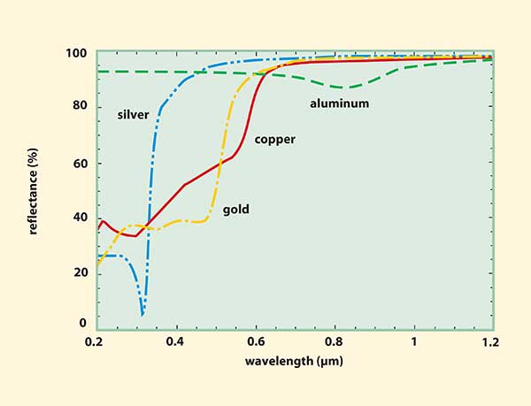
Across the visible spectrum, silver is the most reflective (Figure 1). For UV applications, such as astronomical telescope mirrors, silver is unacceptable and aluminum is the best choice. Unfortunately, aluminum suffers in the region from 0.8 to 1.0 μm, where the reflectance dips well below 90 percent. In an optical system with several mirrors, this can be detrimental to performance. For a reflectance of 85 percent, a system with five mirrors would have a throughput of only 44 percent.

Figure 1. The reflectance of several shiny metals vs. wavelength from 0.2 to 1.2 μm. The reflectance values are calculated using equation 1 with data from references 1 and 2.
Copper and gold are useful only in the red and IR spectral regions. For
situations involving higher durability, less shiny metals are adequate.
For example, rhodium is used for dental mirrors and chromium is used for
rearview mirrors in cars.
Aluminum is fairly stable as a mirror, but silver tarnishes quickly
unless kept in a dry, contamination-free environment. For example, a
silver mirror that can last for months in Albuquerque, N.M., may degrade
within a day in Orlando, Fla. If high reflectance is needed only beyond
0.6 or 0.7 μm, gold is a good choice because it is environmentally
stable. However, even an unprotected aluminum or gold mirror cannot
withstand cleaning with anything but the most gentle cotton ball or
camel hair brush.
A solution to degradation is overcoating the mirror with a dielectric material that is harder than the metal surface. A common overcoat material for visible mirrors is silicon monoxide (SiO). A mirror with a simple dielectric overcoat is called a protected metal mirror. Environmentally stable silver mirrors can be made by including various overcoat layers.4
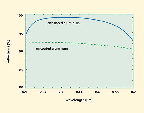
A more complicated coating can be used to increase the reflectance of a metal mirror. Such a coating would consist of several dielectric layers with alternating high and low indices of refraction. The first layer usually has a low index and the last layer, a high index. This type of mirror is called an enhanced metal mirror or an enhanced reflector. With four layers, the reflectance can be enhanced several percent over a limited spectral region (Figure 2).

Figure 2. The reflectance of an enhanced aluminum mirror vs. wavelength compared with the reflectance of an uncoated aluminum surface. The enhanced mirror includes four alternating layers of silicon dioxide and titanium dioxide.
All-dielectric mirror coatings
Mirrors can be made by depositing a stack of alternate high- and low-index dielectric layers on a glass substrate. If one wishes to make a mirror for a given wavelength of light, usually denoted λ0, the thickness of each layer is chosen so that the product of the thickness and the index of refraction of the layer is λ0/4. This is called a λ/4 stack reflector. The first and last layers of the stack are of the high-index material. Increasing the number of layers can increase the reflectance at λ0, but the spectral width of the high-reflectance region is limited. If the λ/4 stack reflector consists of p+1 high-index layers with refractive index nH and p low-index layers with index nL on a substrate with refractive index nS, the maximum reflectance is given by:

where the effective index nE of the λ/4 stack is given by:

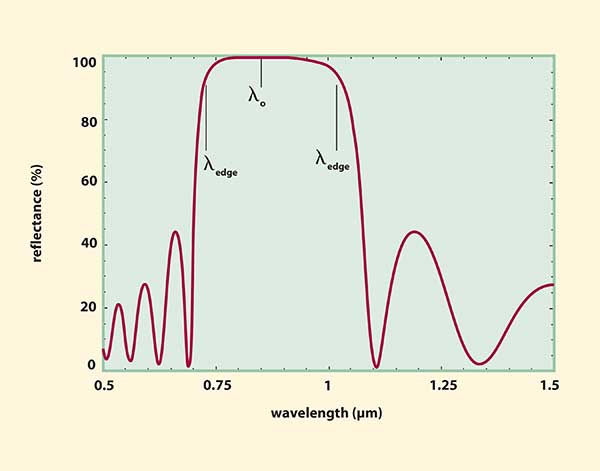
For the 11-layer stack whose reflectance is shown in Figure 3, the following values were used: nH = 2.5, nL = 1.46 and nS = 1.52 with p = 5. The wavelength λedge at each edge of the high-reflectance region defines the width of the reflectance band, as indicated in Figure 3. The two values of λedge are given by:

where

For the reflectance curve in Figure 3, the calculated edge wavelengths are 0.727 and 1.034 μm. Because of the limited width of the high-reflectance region, λ/4 stack mirrors have specific applications. The most common is their use as laser reflectors, either as a part of the laser cavity itself or for the optics that direct the laser beam through the optical system. For example, the 0.85-μm reflector might be used with the laser diode in a CD player. The typical laser reflector usually has between 21 and 27 layers and a maximum reflectance of more than 99.9 percent.

Figure 3. The reflectance of a λ/4 stack, all-dielectric mirror vs. wavelength. The mirror consists of 11 alternating layers of titanium dioxide and silicon dioxide. The reflectance band is centered at λ0 = 0.85 μm and the width of the high-reflectance region is between the two wavelengths marked λedge given by equations 4 and 5.
A λ/4 stack reflector also can be used to filter out or remove a selected portion of the spectrum from an optical system. Such a filter is called a dichroic filter because it separates light of two spectral regions.
A broadband all-dielectric mirror can be made by combining two or more λ/4 stack reflectors with central wavelengths close enough together that the edges of the reflectance bands overlap. Such a mirror is durable and nonconductive and can have more than 99 percent reflectance over the entire visible spectrum. A mirror with such performance might involve as many as 100 layers. The buyer is left with the trade-off between the higher cost of a 100-layer mirror with 99+ percent reflectance and a much less expensive three- or four-layer enhanced aluminum mirror with about 97 percent reflectance.
A final word about optical figure: In cases where optical figure or flatness is important, choose a mirror with fewer layers. The figure of a surface that has been polished to 1/10 of a wavelength will not be adversely affected by a 1000-Å-thick aluminum layer that has thickness variations of several percent. However, a 100-layer coating with thickness variations of 2 percent across the surface (a typical coating uniformity tolerance) would distort the wavefront of the reflected beam by several wavelengths. Amateur astronomers who polish their own telescope mirrors — often to a surface accuracy of λ/10 — must be careful that the figure is not ruined by an aluminum coating with a protective layer that has poor uniformity.
References
1. Handbook of Optical Constants of Solids. Edward D. Palik, ed. (1985). Academic Press.
2. Handbook of Optical Constants of Solids II. Edward D. Palik, ed. (1991). Academic Press.
3. Handbook of Optical Constants of Solids III. Edward D. Palik, ed. (1998). Academic Press.
4. Wolfe, Jesse D., Ronald E. Laird, C.K. Carniglia and J.P. Lehan (1995). Durable silver-based antireflection coatings and enhanced mirrors. OPTICAL INTERFERENCE COATINGS, 1995 Technical Digest Series, 17:115-117.