A perfect lens can produce a perfect image. But seven primary lens aberrations can blur or distort the image instead, and they should be considered when creating an optical system.
Bruce H. Walker, Walker Associates
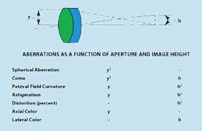
A lens collects light from a point on an object and focuses it to a corresponding conjugate point on an image. Under most conditions, the lens fails at this task because of some error in the precision with which it focuses this light. Rather than a true point image, the lens produces a blur circle. It is the function of the optical designer to assure that this blur circle is sufficiently small to allow the required resolution or image quality. The inability of a lens to form a perfect image is caused by lens aberrations. The following paragraphs will describe the seven aberrations and discuss some of the salient points of each.
Spherical aberration
Spherical aberration is the imaging error found when a lens is focusing an axial bundle of monochromatic light. In the presence of spherical aberration, each zone or annulus of the lens aperture has a slightly different focal length.
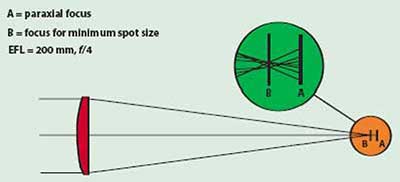
Figure 1. Spherical aberration in a planoconvex lens.
The result can be seen in Figure 1. The enlarged view shows the actual intersection of focused rays with the image surface. At the paraxial focus A, all rays close to the axis of the lens are focused accurately. The rays from zones farther from the axis are focused short of the paraxial focus. The farther the rays are from the axis, the greater is this error in focus. This lack of a common focus for all zones of the lens is spherical aberration.
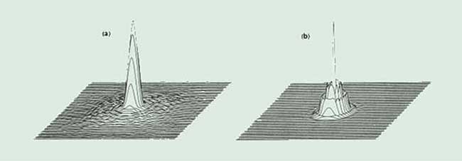
Figure 2. Point spread functions for the lens in Figure 1 at the paraxial focus (a) and focus for minimum spot size (b).
In Figure 1, there is a point, B, just short of the paraxial focus where the blur circle, or spot size caused by spherical aberration, is minimized. Figure 2 shows the intensity spread function for the paraxial and minimum spot size focus positions. Analysis of these spread functions reveals that at the paraxial focus there is a bright spot about 0.02 mm in diameter, surrounded by a circle of flare about 0.08 mm in diameter.
In the case of focus for minimum spot size, the central spot is slightly greater, about 0.025 mm in diameter, while the visible flare diameter has been reduced to less than 0.04 mm. In almost all applications where spherical aberration is present, the overall image quality is best when the lens is focused close to the point of minimum spot size.
Coma
Coma is an aberration that afflicts off-axis light bundles in a manner quite similar to the way in which spherical aberration affects axial bundles. As shown in Figure 3, when an off-axis bundle is incident on a lens afflicted with coma, each annulus focuses onto the image plane at a slightly different height and with a different spot size. The result is an overall spot that is comatic in shape, having a bright central core with a triangular flare extending toward the optical axis of the lens.
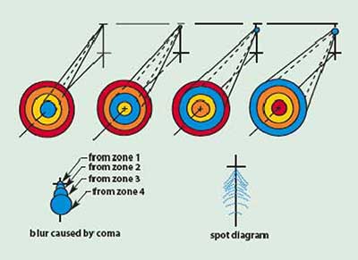
Figure 3. Illustration of the off-axis aberration, coma.
For a pair of simple lenses arranged symmetrically as in a relay lens system, or a complex lens that has some degree of symmetry, a significant reduction in the amount of coma is found. This important characteristic is used in the design of many lenses and instruments such as borescopes and submarine periscopes. The residual coma in a lens system is usually combined with other off-axis aberrations, making its individual contribution to final image quality difficult to evaluate.
Field curvature
In most optical systems, the final image must be formed on a plane or flat surface. Unfortunately, most optical systems tend to form that image on a curved surface. The nominal curvature (1/radius) of that surface is referred to as the Petzval, or field curvature of the lens. For simple lenses this curvature is equal to approximately 2/3 of the lens power. When the lens is free of other off-axis aberrations, the image is formed on the Petzval surface. When astigmatism is present (which is most often the case) the Petzval surface has no real significance as far as actual imaging of the lens system is concerned.
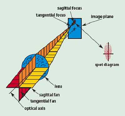
Figure 4. Illustration of astigmatism.
Astigmatism
When astigmatism is present in a lens system, fans of rays of differing orientations at the lens aperture tend to focus on differing curved surfaces. Figure 4 shows two fans of rays passing through a simple lens and indicates how they are focused. The spot diagram in Figure 4 shows that the presence of astigmatism causes the ideal circular point image to be blurred into an elliptical patch.
The field curves shown in Figure 5 represent another method of illustrating the aberrations of field curvature and astigmatism. These curves represent a cross section of half the image surface from the optical axis out to the edge of the field. Figure 5a shows a set of field curves for a lens afflicted with both field curvature and astigmatism. If we think of the image as a spoked wheel centered on the optical axis, the rim of the wheel is in focus at the tangential image surface, while the spokes are in focus at the sagittal surface.
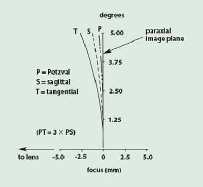
Figure 5a. Illustration of field curvature and astigmatism in a simple lens.
Astigmatism is, by definition, the difference between the tangential and sagittal field curves. If the tangential and sagittal surfaces are coincident, then the lens is said to be free of astigmatism. In this case, the image is formed on the Petzval surface. When astigmatism is present, the tangential field departure from the Petzval surface is three times the departure of the sagittal field (Figure 5a). In most cases it is not possible to correct field curvature and astigmatism to zero, but satisfactory image quality usually can be achieved by balancing residual astigmatism with inherent field curvature as illustrated in Figure 5b.
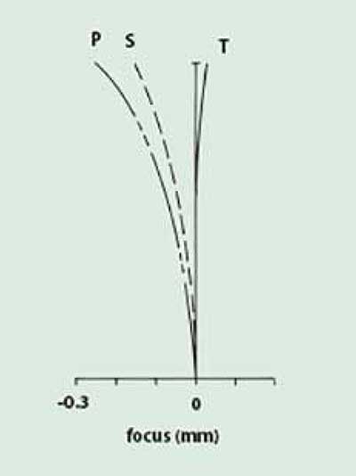
Figure 5b. Illustration of the introduction of negative astigmatism to balance field curvature.
Distortion
Distortion is a unique aberration in that it does not affect the quality of the image in terms of sharpness or focus. Rather, distortion affects the shape of the image, causing it to depart from a true scaled duplicate of the object. Figure 6b represents a lens system free of distortion that produces a true reproduction of the checkerboard object. If the system suffers from positive distortion, then the off-axis points are imaged at distances greater than nominal, creating the pincushion effect seen in 6a. On the other hand, if the system exhibits negative distortion, the resulting image assumes a barrel shape as seen in Figure 6c. With the exception of certain metrological systems, where critical measurements are taken from the image, distortion errors in the 5 to 10 percent region usually are deemed acceptable.
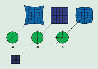
Figure 6. Illustration of distortion: (a) approximately 15 percent positive (pincushion) distortion; (b) zero distortion; and (c) approximately 10 percent negative (barrel) distortion.
The five aberrations presented to this point have been monochromatic aberrations, generally computed at the central wavelength for the lens system. If the lens is to be used over an extended spectral bandwidth, the following two chromatic aberrations must also be considered.
Axial color
For all optical glasses, the index of refraction varies as a function of wavelength; the index is greater for shorter (blue) wavelengths. Also, the rate at which the index changes is greater at the shorter wavelengths. In a simple lens this causes each wavelength to focus at a different point along the optical axis. This chromatic spreading of the light is known as dispersion.
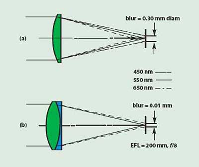
Figure 7. Axial color in a simple lens (a) and in an achromat (b) of identical focal length and speed (f/#).
Figure 7a illustrates a simple lens focusing a bundle of white light covering the spectral band from 450 to 650 nm. If the focus is set for the middle of the band, as shown, the blur circle consists of a green central core with a halo of purple (red and blue) surrounding it. Except in very unusual cases, such as laser systems or nearly monochromatic systems, axial color is an aberration that must be dealt with in order to achieve usable image quality. This can be accomplished by converting the simple lens into an achromatic doublet as shown in Figure 7b. The two glass types selected correct the primary axial color by bringing the two extreme wavelengths to a common focus. In the lens illustrated, a reduction of 30 times in blur-circle size has been realized by the achromatization of this simple lens.
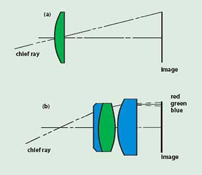
Figure 8. A simple lens with little chief ray refraction (a) has little lateral color. An eyepiece design (b) where substantial nonsymmetrical refraction of the chief ray exists will be afflicted with lateral color.
Lateral color
The second chromatic aberration (and the last of the seven primary lens aberrations) is lateral color. For on-axis light bundles, the optical axis of the lens coincides with the central ray in that bundle. For off-axis bundles, the corresponding central ray is called the chief ray, or principal ray. The height of the chief ray at the image plane defines image size. If lateral color exists in the lens system, this chief ray is dispersed, causing the differing wavelengths to be imaged at different heights on the image plane. The result is a chromatic, radial blur for off-axis image points.
In the case of a simple lens with the chief ray passing through its center, there is little refraction of that ray and, therefore, little lateral color. A system that is symmetrical about the point where the chief ray crosses the optical axis (the aperture stop) has little or no lateral color because the aberration tends to cancel itself as the chief ray traverses the symmetrical halves of the system.
 The eyepiece is a classic example of a lens form that produces large amounts of chief ray refraction that is not symmetrical about the aperture stop. As a result, in most eyepiece designs lateral color is a major contributor to degradation of off-axis image quality. Figure 8 illustrates the chief ray path through a simple lens 8a and an eyepiece 8b. The presence or lack of lateral color is shown in each case.
Conclusion
This completes the review of the seven primary lens aberrations. The optical designer must evaluate the potential contribution of each aberration to final system performance and adjust the configuration of the optical system to achieve satisfactory performance.
Acknowledgment
This article is derived from an earlier piece prepared by the author for use in the Optics and Filters catalog produced by Oriel Corp. The company’s permission to use portions of that piece is gratefully acknowledged.